Assertion : Long distance power transmission is done at high voltage.
Reason : At high voltage supply power losses are less.
AIIMS 2014, Easy


Download our appand get started for free
Experience the future of education. Simply download our apps or reach out to us for more information. Let's shape the future of learning together!No signup needed.*
Similar Questions
- 1$A$ potentiometer wire has length $10\, m$ and resistance $10\,\Omega$ . It is connected to a battery of $EMF$ $11\, volt$ and internal resistance $1\, \Omega$ , then the potential gradient in the wire is ............... $V/m$View Solution
- 2The resistivity $(\rho)$ of semiconductor varies with temperature. Which of the following curve represents the correct behaviourView Solution
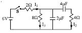
- 3In the circuit shown in the figure, the switch $S$ is initially open and the capacitor is initially uncharged. $ I_1, I_2$ and $I_3$ represent the current in the resistance $2\,\Omega , 4\,\Omega $ and $8\,\Omega$ respectively.View Solution
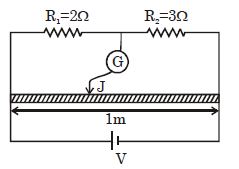
- 4In a meter bridge experiment, initially the jockey is at null point. Now resistance $R_1$ $\&$ $R_2$ is interchanged. Shift in the position of jockey is ................ $cm$View Solution
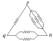
- 5Six equal resistances are connected between points $P$, $Q$ and $R$ as shown in the figure. Then the net resistance will be maximum betweenView Solution
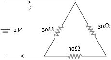
- 6View SolutionThe current in the adjoining circuit will be
- 7Two electric bulbs ($60\,W$ and $100\,W$ respectively) are connected in series. The current passing through them isView Solution
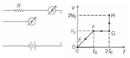
- 8In the circuit shown below (on the left) the resistance and the emf source are both variable. The graph of seven readings of the voltmeter and the ammeter ( $V$ and $I$, respectively) for different settings of resistance and the emf, taken at equal intervals of time $\Delta t$, are shown below (on the right) by the dots connected by the curve $E F G H$. Consider the internal resistance of the battery to be negligible and the voltmeter an ammeter to be ideal devices. (Take, $R_0 \equiv \frac{V_0}{I_0}$ ).View Solution
Then, the plot of the resistance as a function of time corresponding to the curve $E F G H$ is given by
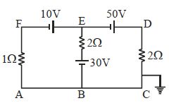
- 9The potential at point $E$ for the given figure is ................ $\mathrm{V}$View Solution
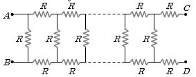
- 10In the figure, the value of resistors to be connected between $C$ and $D$ so that the resistance of the entire circuit between $A$ and $B$ does not change with the number of elementary sets used isView Solution