Question
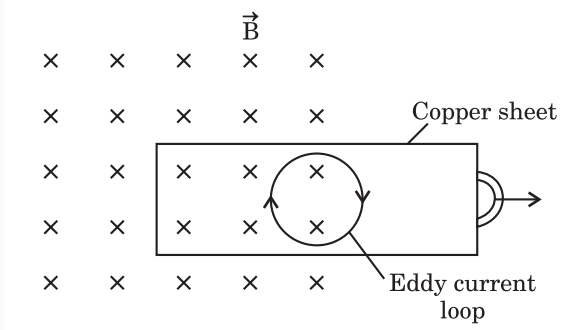
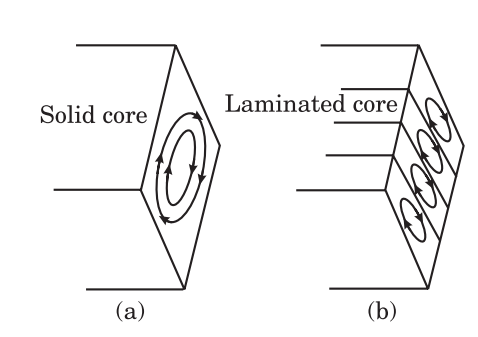
Define eddy currents. How are they produced? In what sense are these currents undesirable in a transformer and how are these reduced in a device ?

Answer

Eddy Currents : In 1824 Gambey discovered that the oscillations of a magnet are rapidly damped if a copper sheet is placed under it and close to it. In 1895 Facault observed that when a metal piece is moved in a constant magnetic field or a varying magnetic field is subjected to the metal piece then the magnetic flux linked with the metal piece changes due to which induced current is generated in the whole volume of the piece. According to Lenz's law these currents oppose the change in magnetic flux. These currents look like eddies or whirlpool's in a fluid and are called eddy currents. These are also called Facault current after the name of their discoverer.
Image
In adjoining figure, a copper sheet in the plane of the paper and a magnetic field is subjected is placed to it in the perpendicular direction to the plane of the paper directed inward represented by cross signs. If we withdraw the sheet out of the field, there is a decrease in its area A within the field and so the magnetic flux $(\Phi= BA )$ linked with the sheet also decreases. Because of this flux change, current loops are induced in the sheet coming out of the field and according to Lenz's law direction of currents is such that the magnetic field produced due to them is in the same direction as the original magnetic field. Thus, eddy currents oppose the decrease in magnetic flux i.e. the drawing out of the sheet. Similarly, if we insert the sheet into the magnetic field the eddy currents are generated in opposite direction to the previous one and oppose the entry of the sheet into the field.
Image
Eddy Currents undesirable in a device (transformer) and means of their reduction : Eddy currents produce a large amount of heat. This heating effect of eddy currents is undesirable in a number of cases like dynamos, transformers, etc. where the coil is wound on iron core. On the other hand, the heating effect of eddy currents is used to make induction furnaces. Similarly, the braking effect of eddy currents is also undesirable in a number of cases. On the other hand, the braking effect of eddy currents is used in electric brakes and ballistic galvanometers. Let us now see how the breaking and heating effects of eddy currents can be minimised.
The solid iron core [Fig. (a)] is divided into a number of thin sheets as shown in Fig. (b). These thin sheets are electrically insulated from each other. Moreover, these sheets are so placed that the path of the induced eddy currents is broken by the insulating material between the sheets. In this way, the eddy currents are considerably reduced. Such cores are called laminated cores as used in transformer.

Need a full question paper?

Generate a complete, print-ready paper with questions like this in minutes — across 16+ boards, with answer keys.

Start Generating Free

Similar questions

For the $L - C - R$ series $AC$ circuit derive the phase relationship between instantaneous current and voltage, using the phasor diagram.
A horizontal overhead power line carries a current of 90 A in east to west direction. What is the magnitude and direction of magnetic field due to the current 1.5 m in below the line?
When the electron orbiting in hydrogen atom in its ground state moves to the third excited state, show how the de Broglie wavelength associated with it would be affected.
TV signals broadcast by Delhi studio cannot be directly received at Patna which is about 1000km away. But the same signal goes some 36000km away to a satellite, gets reflected and is then received at Patna. Explain.
The simplest and the most widely used capacitor is the parallel plate capacitor. It consists of two large plane parallel conducting plates, separated by a small distance. In the outer regions above the upper plate and below the lower plate, the electric fields due to the two charged plates cancel out. The net field is zero. In the inner region between the two capacitor plates, the electric fields due to the two charged plates add up. The net field is $\frac{\sigma}{\epsilon_0}.$
For a uniform electric field, potential difference between the plates $=$ Electric field x distance between the plates. Capacitance of the parallel plate capacitor is the charge required to supplied to either of the conductors of the capacitor so as to increase the potential difference between then by unit amount.
  1. A parallel plate capacitor is charged and then isolated. The effect of increasing the plate separation on charge, potential and capacitance respectively are:
  1. Increases, decreases, decreases.
  2. Constant, increases, decreases.
  3. Constant, decreases, decreases.
  4. Constant, decreases, increases.
  1. In a parallel plate capacitor, the capacity increases if:
  1. Area of the plate is decreases.
  2. Distance between the plates increases.
  3. Area of the plate is increases.
  4. Dielectric constant decreases.
  1. A parallel plate capacitor has two square plates with equal and opposite charges. The surface charge densities on the plates are $+\sigma$ and $-\sigma$ respectively. In the region between the plates the magnitude of the electric field is:
  1. $\frac{\sigma}{2\epsilon_0}$
  2. $\frac{\sigma}{\epsilon_0}$
  3. $0$
  4. None of these.
  1. If a parallel plate air capacitor consists of two circular plates of diameter $8\ cm$. At what distance should the plates be held so as to have the same capacitance as that of sphere of diameter $20\ cm$?
  1. $9\ mm$
  2. $4\ mm$
  3. $8\ mm$
  4. $2\ mm$
  1. If a charge of $+ 2.0 \times 10^{-8}C$ is placed on the positive plate and a charge of $- 1.0 \times 10^{-8}C$ on the negative plate of a parallel plate capacitor of capacitance $1.2\times10^{-3}\mu\text{F},$ then the potential difference developed between the plates is:
  1. $6.25V$
  2. $3.0V$
  3. $12.5V$
  4. $25V$
To keep valuable instruments away from the earth's magnetic field, they are enclosed in iron boxes. Explain.
ln Young's double slit experiment, the width of the central bright fringe is equal to the distance between the first dark fringes on the two sides of the central bright fringe.
ln given figure below a screen is placed normal to the tine joining the two point coherent source $S_1$ and $S_2$. The interference pattern consists of concentric circles.
  1. The optical path difference at $P$ is:
  1. $\text{d}\Big[1+\frac{\text{y}^2}{2\text{D}}\Big]$
  2. $\text{d}\Big[1+\frac{2\text{D}}{\text{y}^2}\Big]$
  3. $\text{d}\Big[1-\frac{\text{y}^2}{2\text{D}^2}\Big]$
  4. $\text{d}\Big[2\text{D}-\frac{1}{\text{y}^2}\Big]$
  1. Find the radius of the $n^{th}​​​​​​​$ bright fringe.
  1. $\text{D}\sqrt{1\Big(1-\frac{\text{n}\lambda}{\text{d}}\Big)}$
  2. $\text{D}\sqrt{2\Big(1-\frac{\text{n}\lambda}{\text{d}}\Big)}$
  3. $2\text{D}\sqrt{2\Big(1-\frac{\text{n}\lambda}{\text{d}}\Big)}$
  4. $\text{D}\sqrt{2\Big(1-\frac{\text{n}\lambda}{2\text{d}}\Big)}$
  1. If $\text{d}=0.5\text{ mm}.\lambda=5000\mathring{\text{A}}$ and $D = 100\ cm,$ find the value of $n$ for the closest second bright fringe.
  1. $888$
  2. $830$
  3. $914$
  4. $998$
  1. The coherence of two light sources means that the light waves emitted have.
  1. Same frequency.
  2. Same intensity.
  3. Constant phase difference.
  4. Same velocity.
  1. The phenomenon of interference is shown by:
  1. Longitudinal mechanical waves only.
  2. Transverse mechanical waves only.
  3. Electromagnetic waves only.
  4. All of these.
Two friends $A$ and $B$ are standing a distance $x$ apart in an open field and wind is blowing from $A$ to $B$. $A$ beats a drum and $B$ hears the sound $t_1$ time after he sees the event. $A$ and $B$ interchange their positions and the experiment is repeated. This time $B$ hears the drum $t_2$ time after he sees the event. Calculate the velocity of sound in still air $v$ and the velocity of wind $u$. Neglect the time light takes in travelling between the friends.
Consider the situation shown in figure. The two slits $S_1$ and $S_1$ placed symmetrically around the central line are illuminated by monochromatic light of wavelength $\lambda$. The separation between the slits is $d$. The light transmitted by the slits falls on a screen $S_0$ place at a distance $D$ from the slits. The slits $S_3$ is at the central line and the slit $S_4$ is at a distance from $S_3$. Another screen $S_c$ is placed a further distance $D$ away from $S_c$.
  1. Find the path difference if $\text{z}=\frac{\lambda\text{D}}{2\text{d}}$.
  1. $5A^2$
  2. $13A^2$
  3. $7A^2$
  4. $19A^2$
  5. Two monochromatic light waves of amplitudes $3_A$ and $2_A$ interfering at a point have a phase difference of $60^\circ$ .
  6. The intensity at that point will be proportional to:
  7. $\Big(\text{n}+\frac{1}{2}\Big)\lambda$
  8. $\text{n}\lambda$
  9. $\Big(\text{n}-\frac{1}{2}\Big)\lambda$
  10. $\frac{\lambda}{2}$
  11. ln the case of light waves from two coherent sources $S_1$ and $S_2,$ there will be constructive interference at an arbitrary point $P, $ if the path difference $\ce{S_1P - S_2P}$ is:
  12. Concentric circles.
  13. Points.
  14. Straight lines.
  15. Semi $-$ circles.
  16. Two coherent point sources $S_1$ and $S_2$ are separated by a small distanced as shown in figure. The fringes obtained on the screen will be:
  17. $4$
  18. $2$
  19. $\infty$
  20. $1$
  21. Find the ratio of the maximum to minimum intensity observed on $S_c$ if $\text{z}=\frac{\lambda\text{D}}{\text{d}}$
  22. $\lambda$
  23. $\frac{\lambda}{2}$
  24. $\frac{3}{2\lambda}$
  25. $2\lambda$
Calculate $\frac{\text{n(T)}}{\text{n}(1000\text{K})}$ for tungsten emitter at T = 300K, 2000K and 3000K, where n(T) represents the number of thermions emitted per second by the surface at temperature T. Work function of tungsten is 4.52eV.