Question
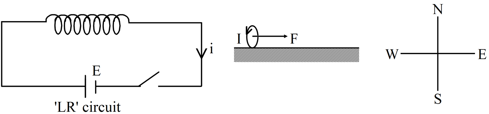
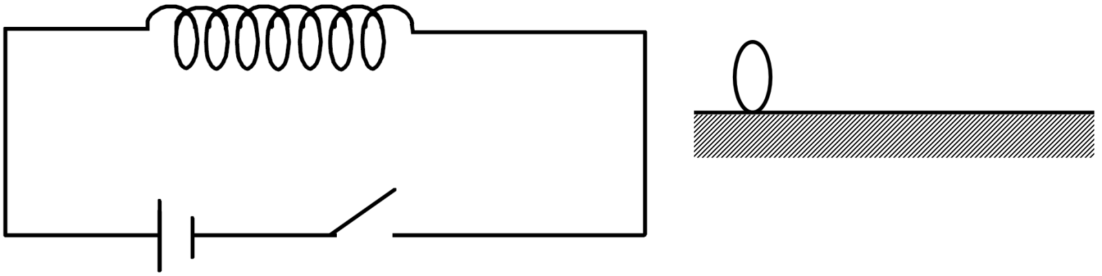
Figure shows a horizontal solenoid connected to a battery and a switch. A copper ring is placed on a frictionless track, the axis of the ring being along the axis of the solenoid. As the switch is closed, the ring will:
  1. Remain stationary.
  2. Move towards the solenoid.
  3. Move away from the solenoid.
  4. Move towards the solenoid or away from it depending on which terminal (positive or negative) of the battery is connected to the left end of the solenoid.

Answer

  1. Move away from the solenoid.
Explanation:

$\text{e}=-\text{L}\frac{\text{di}}{\text{dt}}$
Current flow in the CKt is clock wise direction, due to Mutual Induction current flow in the loop anti clockwise direction. The net force applied on the loop in east direction. So we can say that the ring will move away from the solenoid.

Need a full question paper?

Generate a complete, print-ready paper with questions like this in minutes — across 16+ boards, with answer keys.

Start Generating Free

Similar questions

A cycle wheel with 64 spokes is rotating with N rotations per second at right angles to horizontal component of magnetic field. The induced emf generated between its axle and rim is E. If the number of spokes is reduced to 32 then the value of induced emf will be:
A proton and an electron are accelerated by the same potential difference. Let $\lambda_\text{e}$ and $\lambda_\text{p}$ denote the de Broglie wavelengths of the electron and the proton respectively.
In Rutherford scattering experiment, what will be the correct angle for α scattering for an impact parameter b = 0(a) 90°(b) 270°(c) 0°(d) 180°
       
A charged particle goes undeflected in a region containing an electric and a magnetic field. It is possible that
The dominant mechanisms for motion of charge carriers in forward and reverse biased silicon P-N junctions are (a) Drift in forward bias, diffusion in reverse bias(b) Diffusion in forward bias, drift in reverse bias(c) Diffusion in both forward and reverse bias(d) Drift in both forward and reverse bias


Three long, straight and parallel wires carrying currents are arranged as shown in figure. The force experienced by $10 \ cm$ length of wire $Q$ is
The electric potential is measured in:
The lead marked with the arrow is the _______.
The resistance of a discharge tube is(a) Ohmic(b) Non-ohmic(c) Both (a) and (b)(d) Zero
       
Two batteries of $\text{e.m.f.}\ 4V$ and $8 V$ with internal resistances $1 W$ and $2 W$ are connected in a circuit with a resistance of $9 W$ as shown in figure. The current and potential difference between the points $P$ and $Q$ are