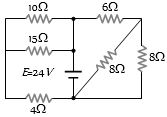
Find the equivalent resistance across the terminals of source of $e.m.f$. $24\, V$ for the circuit shown in figure .............. $\Omega$
Medium
Download our app for free and get started
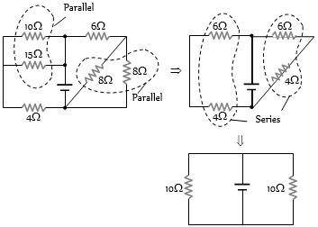
(c) Given circuit can be reduced to a simple circuit as shown in figures below
i.e. ${R_{eq}} = 5\,\Omega $.
i.e. ${R_{eq}} = 5\,\Omega $.

Download our appand get started for free
Experience the future of education. Simply download our apps or reach out to us for more information. Let's shape the future of learning together!No signup needed.*
Similar Questions
- 1Two resistors of resistance $R_1$ and $R_2$ having $R_1 > R_2$ are connected in parallel. For equivalent resistance $R$, the correct statements isView Solution
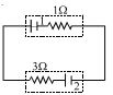
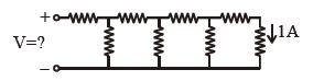
- 2Each element in the finite chain of resistors shown in the figure is $\,1\,\Omega $ . A current of $1\, A$ flows through the final element. Then what is the potential difference $V$ across input terminals of the chain .................. $\mathrm{volt}$View Solution
- 3By using only two resistance coils-singly, in series, or in parallel one should be able to obtain resistances of $3$, $4$, $12$ and $16\, ohms$. The separate resistances of the coil areView Solution
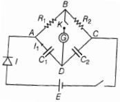
- 4ln the circuit in the figure, if no current flows through the galvanometer when the key $K$ is closed, the bridge is balanced. The balancing condition for bridge isView Solution
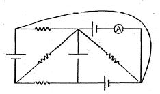
- 5In the circuit diagram shown, each battery is ideal having an e.m.f. of $1\ volt$. Each resistor has a resistance of $1\Omega $ Ammotor$(A)$ has a resistance of $1\Omega $ Find the reading of the ammeter and the total thermal power produced in the circuitView Solution
- 6View SolutionA heater coil is cut into two equal parts and only one part is now used in the heater. The heat generated will now be
- 7Two identical cells each of emf $1.5\,V$ are connected in series across a $10\,\Omega$ resistance. An ideal voltmeter connected across $10\,\Omega$ resistance reads $1.5\,V$. The internal resistance of each cell is $......\Omega$.View Solution
- 8View SolutionWhich of the following statement is correct
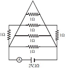
- 9In the circuit shown in Figure the ammeter reads a current ............. $A$View Solution
- 10In the figure shown, battery $1$ has $\mathrm{emf}$ $= 6\, V$ and internal resistance $= 1 \,\Omega$. Battery $2$ has $\mathrm{emf}$ $= 2\,V$ and internal resistance $= 3\, \Omega$ . The wires have negligible resistance. What is the potential difference across the terminals of battery $2$ ? ................ $V$View Solution