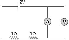
In the circuit shown, $A$ and $V$ are ideal ammeter and voltmeter respectively. Reading of the voltmeter will be ............... $V$
Easy
Download our app for free and get started
(d) Zero (No potential difference across voltmeter).

Download our appand get started for free
Experience the future of education. Simply download our apps or reach out to us for more information. Let's shape the future of learning together!No signup needed.*
Similar Questions
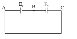
- 1Two cells are connected in opposition as shown. Cell $\mathrm{E}_1$ is of $8 \mathrm{~V}$ emf and $2 \ \Omega$ internal resistance; the cell $E_2$ is of $2 \mathrm{~V}$ emf and $4\ \Omega$ internal resistance. The terminal potential difference of cell $\mathrm{E}_2$ is:View Solution
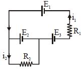
- 2The current $i_1$ and $i_2$ through the resistor $R_1 (= 10\,\Omega )$ and $R_2 (=30 \,\Omega )$ in the circuit diagram with $E_1 = 3\,V, E_2 = 3\,V$ and $E_3 = 2\,V$ are respectively:View Solution
- 3View SolutionWhen electric bulbs of same power, but different marked voltage are connected in series across the power line, their brightness will be :
- 4An electric bulb is designed to draw power $P_0$ at voltage $V_0$. If the voltage is $V$ it draws a power $P$. ThenView Solution
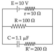
- 5As show in the figure, in steady state, the charge stored in the capacitor is....... $\times 10^{-6}\,C$.View Solution
- 6The temperature coefficient of resistance for a wire is $0.00125\,^oC$. At $300\,K$ its resistance is $1\, ohm$. The temperature at which the resistance becomes $2\, ohm$ is .......... $K$View Solution
- 7The energy dissipated by a resistor is $10 \,mJ$ in $1\,s$ when an electric current of $2\, mA$ flows through it. The resistance is $....... \Omega$View Solution
(Round off to the Nearest Integer)
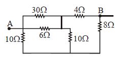
- 8The equivalent resistance across $AB$ would be ............ $\Omega$View Solution
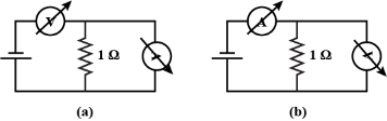
- 9A student uses the resistance of a known resistor $(1 \,\Omega)$ to calibrate a voltmeter and an ammeter using the circuits shown below. The student measures the ratio of the voltage to current to be $1 \times 10^3 \,\Omega$ in circuit $(a)$ and $0.999 \,\Omega$ in circuit $(b)$. From these measurements, the resistance (in $\Omega$ ) of the voltmeter and ammeter are found to be close toView Solution
- 10Resistance of a carbon resistor determined from colour codes is $(22000 \pm 5 \%) \Omega$. The colour of third band must be :View Solution