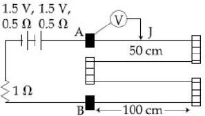
In the circuit shown, a four wire potentiometer is made of a $400\, cm$ long wire, which extends between $A$ and $B$. The resistance per unit length of the potentiometer wire is $r = 0.01\, \Omega /cm$. If an ideal voltmeter is connected as shown with jockey $J$ at $50\, cm$ from end $A$, the expected reading of the voltmeter will be: ............... $V$
JEE MAIN 2019, Medium
Download our app for free and get started
Resistance of wire $A B=400 \times 0.01=4 \,\Omega$ $\mathrm{i}=\frac{3}{6}=0.5\, \mathrm{A}$
Now voltmeter reading $=$ $i$ (Resistance of $50 \,\mathrm{cm}$ length)
$=(0.5 \mathrm{A})(0.01 \times 50)=0.25$ $volt$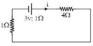

Download our appand get started for free
Experience the future of education. Simply download our apps or reach out to us for more information. Let's shape the future of learning together!No signup needed.*
Similar Questions
- 1The electric intensity $E$, current density $j$ and specific resistance $k$ are related to each other by the relationView Solution
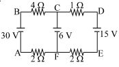
- 2The figure shows a network of four resistances and three batteries The current through the branch $CF$ is ............... $A$View Solution
- 3When a resistor of $11 \,\Omega$ is connected in series with an electric cell, the current flowing in it is $0.5\, A$. Instead, when a resistor of $5 \,\Omega$ is connected to the same electric cell in series, the current increases by $0.4\, A$. The internal resistance of the cell is ................ $\Omega$View Solution
- 4Resistance of a wire at $0^{\circ} \mathrm{C}, 100^{\circ} \mathrm{C}$ and $t^{\circ} \mathrm{C}$ is found to be $10 \Omega, 10.2 \Omega$ and $10.95 \Omega$ respectively. The temperature $t$ in Kelvin scale is $\qquad$View Solution
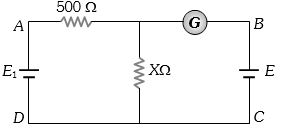
- 5In the adjoining circuit, the battery ${E_1}$ has an $e.m.f.$ of $12\,volt$ and zero internal resistance while the battery $E$ has an $e.m.f.$ of $2\,volt$. If the galvanometer $G$ reads zero, then the value of the resistance $X$ in $ohm$ isView Solution
- 6View SolutionWhich of the following statement is correct
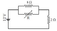
- 7The value of the resistance $R$ in figure is adjusted such that power dissipated in the $2\,\Omega $ resistor is maximum. Then the power dissipated in the $2\,\Omega $ will be ................ $W$View Solution
- 8$n$ identical bulbs, each designed to draw a power $p$ from a certain voltage supply, are joined in series across that supply. The total power which they will draw isView Solution
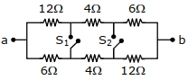
- 9In the given figure switches $S_{1}$ and $S_{2}$ are in open condition. The resistance across $a b$ when the switches $S_{1}$ and $S_{2}$ are closed is $...\,\Omega$View Solution
- 10Equivalent resistance between the adjacent corners of a regular $n$-sided polygon of uniform wire of resistance $R$ would be:View Solution