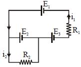
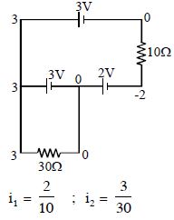
The current $i_1$ and $i_2$ through the resistor $R_1 (= 10\,\Omega )$ and $R_2 (=30 \,\Omega )$ in the circuit diagram with $E_1 = 3\,V, E_2 = 3\,V$ and $E_3 = 2\,V$ are respectively:
Medium


Download our appand get started for free
Experience the future of education. Simply download our apps or reach out to us for more information. Let's shape the future of learning together!No signup needed.*
Similar Questions
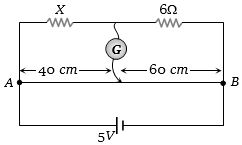
- 1In the circuit shown, a meter bridge is in its balanced state. The meter bridge wire has a resistance $0.1\, ohm/cm$. The value of unknown resistance $X$ and the current drawn from the battery of negligible resistance isView Solution
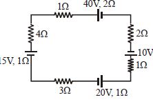
- 2View SolutionFind the current in the loop.
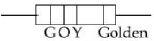
- 3View SolutionA carbon resistance has a following colour code. What is the value of the resistance?
- 4The $n$ rows each containing $m$ cells in series are joined in parallel. Maximum current is taken from this combination across an external resistance of $3 \,\Omega$ resistance. If the total number of cells used are $24$ and internal resistance of each cell is $0.5 \,\Omega$ thenView Solution
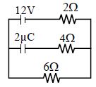
- 5Find the charge on the capacitor $C$ in the given circuit .................. $\mu C$View Solution
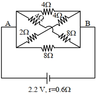
- 6In the given figure, the $emf$ of the cell is $2.2\, {V}$ and if internal resistance is $0.6\, \Omega$. Calculate the power dissipated in the whole circuit: (in $W$)View Solution
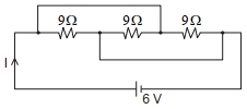
- 7The current $I$ flowing through the given circuit will be $.....A$.View Solution
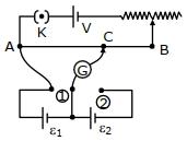
- 8In the given potentiometer circuit arrangement, the balancing length ${AC}$ is measured to be $250$ ${cm}$. When the galvanometer connection is shifted from point $(1)$ to point $(2)$ in the given diagram, the balancing length becomes $400\, {cm}$. The ratio of the emf of two cells, $\frac{\varepsilon_{1}}{\varepsilon_{2}}$ is -View Solution
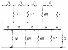
- 9For what value of the resistor $X$ will the equivalent resistance of the two circuits shown be the same?View Solution
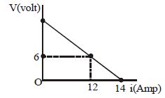
- 10$10\, Cells$, each of $emf$ $'E'$ and internal resistance $'r'$, are connected in series to a variable external resistance. Figure shows the variation of terminal potential difference of their combination with the current drawn from the combination.$Emf$ of each cell is ................ $V$View Solution