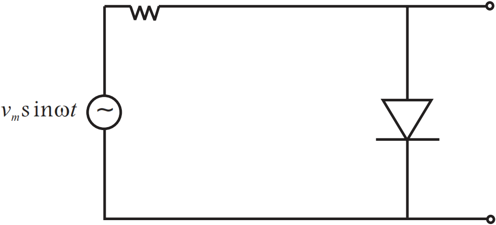
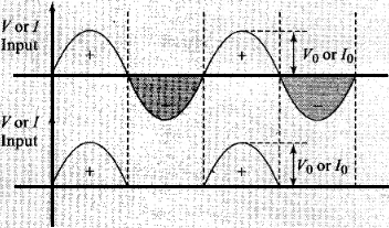
When the diode is forward biased during positive half cycle of input AC voltage, the resistance of p-n junction is low. The current in the circuit is maximum. In this situation, a maximum potential difference will appear across resistance connected in a series of circuit. This result into zero output voltage across p-n junction.
And when the diode is reverse biased during negative half cycle of AC voltage, the p-n junction is reverse biased. The resistance of p-n junction becomes high which will be more than resistance in series. That is why, there will be voltage across p-n junction with negative cycle in output, hence option (c) is correct.
Need a full question paper?
Generate a complete, print-ready paper with questions like this in minutes — across 16+ boards, with answer keys.