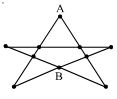
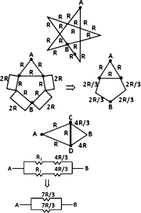
The resistance of all the wires between any two adjacent dots is $R$. Then equivalent resistance between $A$ and $B$ as shown in figure is :
Diffcult


Download our appand get started for free
Experience the future of education. Simply download our apps or reach out to us for more information. Let's shape the future of learning together!No signup needed.*
Similar Questions
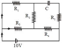
- 1An ideal cell of emf $10\, V$ is connected in circuit shown in figure. Each resistance is $2\, \Omega .$ The potential difference (in $V$) across the capacitor when it is fully charged isView Solution
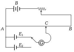
- 2The circuit shown here is used to compare the $e.m.f.$ of two cells ${E_1}$ and ${E_2}({E_1} > {E_2})$. The null point is at $C$ when the galvanometer is connected to ${E_1}$. When the galvanometer is connected to ${E_2}$, the null point will beView Solution
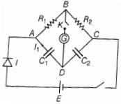
- 3ln the circuit in the figure, if no current flows through the galvanometer when the key $K$ is closed, the bridge is balanced. The balancing condition for bridge isView Solution
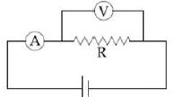
- 4The actual value of resistance $R$, shown in the figure is $30\,\Omega $. This is measured in an experiment as shown using the standard formula $R = \frac{V}{I}$ where $V$ and $I$ are the readings of the voltmeter and ammeter, respectively. If the measured value of $R$ is $5\%$ less, then the internal resistance of the voltmeter is ................. $\Omega$View Solution
- 5Tend identical cells each of potential $E$ and internal resistance $r$ are connected in series to form a closed circuit. An ideal voltmeter connected across three cells, will read $...........E$View Solution
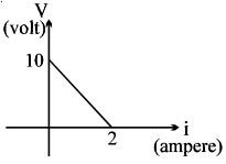
- 6$A$ battery of $\mathrm{emf}$ $E$ and internal resistance $r$ is connected across a resistance $R$. Resistance $R$ can be adjusted to any value greater than or equal to zero. Agraph is plotted between the current $(i)$ passing through the resistance and potential difference $(V) $ across it. Select the correct alternative $(s)$.View Solution
- 7In an electrical cable there is a single wire of radius $9\, mm$ of copper. Its resistance is $5\,\Omega $. The cable is replaced by $6$ different insulated copper wires, the radius of each wire is $3\,mm$. Now the total resistance of the cable will be ............... $\Omega$View Solution
- 8If $n,\,e,\,\tau $ and $m$ respectively represent the density, charge relaxation time and mass of the electron, then the resistance of a wire of length $l$ and area of cross-section $A$ will beView Solution
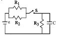
- 9The circuit shown in the figure consists of a battery of $emf$ $\varepsilon = 10 \,V$ ; a capacitor of capacitance $C = 1.0$ $ \mu F$ and three resistor of values $R_1 = 2$ $\Omega$ , $R_2 = 2$ $\Omega$ and $R_3 = 1$ $\Omega$ . Initially the capacitor is completely uncharged and the switch $S$ is open. The switch $S$ is closed at $t = 0.$View Solution
- 10The specific resistance of a wire is $\rho $, its volume is $3\,{m^3}$ and its resistance is $3\, ohms$, then its length will beView Solution