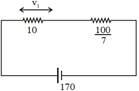
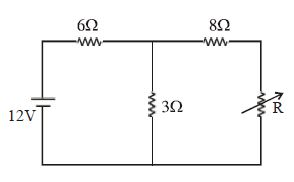
The voltage across the $10\, \Omega$ resistor in the given circuit is $x$ volt.
The value of $'x'$ to the nearest integer is..........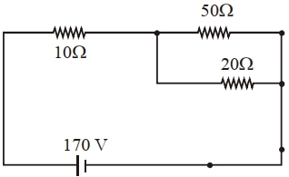
JEE MAIN 2021, Medium


Download our appand get started for free
Experience the future of education. Simply download our apps or reach out to us for more information. Let's shape the future of learning together!No signup needed.*
Similar Questions
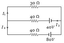
- 1In the given circuit the current $I_1$ is .............. $A$View Solution
- 2Assertion : When current through a bulb decreases by $0.5\%$, the glow of bulb decreases by $1\%$.View Solution
Reason : Glow (Power) which is directly proportional to square of current.
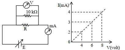
- 3To determine the resistance ($R$) of a wire, a circuit is designed below, The $V-I$ characteristic curve for this circuit is plotted for the voltmeter and the ammeter readings as shown in figure. The value of $\mathrm{R}$ is . . . . . . .$\Omega$View Solution
- 4Voltmeter reads potential difference across the terminals of an old battery as $1.2\,volt$ , while a potentiometer reads $1.4\,volt$ . The internal resistance of battery is $40\,\Omega $ , then voltmeter resistance is .............. $\Omega$View Solution
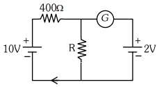
- 5If the galvanometer $G$ does not show any deflection in the circuit shown, the value of $R$ is given by $............\Omega$View Solution
- 6$A$ wire of length $L$ and $3$ identical cells of negligible internal resistances are connected in series. Due to the current, the temperature of the wire is raised by $\Delta T$ in time $t. N$ number of similar cells is now connected in series with a wire of the same material and cross section but of length $2L$. The temperature of the wire is raised by the same amount $\Delta T$ in the same time $t$. The value of $N$ is :View Solution
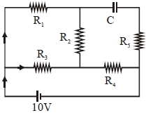
- 7An ideal cell of emf $10\, V$ is connected in circuit shown in figure. Each resistance is $2\, \Omega .$ The potential difference (in $V$) across the capacitor when it is fully charged isView Solution
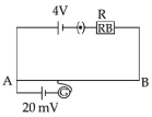
- 8As shown in the figure, a potentiometer wire of resistance $20\,\Omega$ and length $300\,cm$ is connected with resistance box (R.B.) and a standard cell of emf $4\,V$. For a resistance ' $R$ ' of resistance box introduced into the circuit, the null point for a cell of $20\,mV$ is found to be $60\,cm$. The value of ' $R$ ' is $.....\Omega$View Solution
- 9The maximum power delivered to resistance $R$ is ............... $W$View Solution
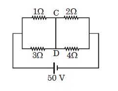
- 10In the given circuit diagram, find the current passing through wire $CD$ (in ampere)View Solution