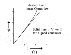
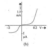
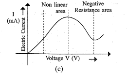
(1) In some devices V and I are not proportional to each other.
(2) The relation between V and I depends on the sign of V. In other words, if I is the current for a certain value of V , then reversing the direction of V keeping its magnitude fixed, does not produce a current of the same magnitude as I in the opposite direction. This happens in case of diode.
(3) The relation between V and I is not unique means there are more than one value of V for the same current I. for example, GaAs (Gallium Arsenide).
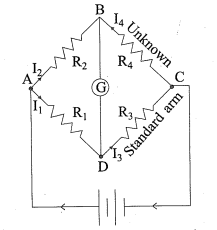
→The circuit shown in the figure is called the wheatstone bridge. It uses four resistors $R_1, R_2$, $R _3$ and $R _4$ out of them three resistors are known and one is unknown, wheatstone bridge is used to find the value of unknown resistance. →As shown in the figure, across one pair of diagonally opposite points (A and C in the figure) a source is connected hence AC is called the battery arm. →Between the other two vertices, B and D , a galvanomenter G is connected hence BD is called the galvanometer arm. →When battery is connected, the currents flowing through the resistors $R_1, R_2, R_3$ and $R_4$ are $I_1$, $I _2, I _3$ and $I _4$ respectively. →Here, there resistors are chosen in such a way that current flowing through galvanometer is zero $\left(I_g=0\right.$ ). →When the current flowing through the galvanometer becomes zero, the bridge is said to be in balanced condition. →From the figure, in balanced condition $I _1= I _3 \text { and } I _2= I _4$ →Applying Kirchhoff's loop rule to closed loop $\begin{array}{l} A - D - B - A \\ - I _1 R _1+0+ I _2 R _2=0 \\ \therefore I _1 R _1= I _2 R _2 \end{array}$ →Applying similarly, for closed loop $C - B - D - C$ $\begin{aligned} & I _4 R _4+0- I _3 R _3=0 \\ \therefore & I _3 R _3= I _4 R _4 \end{aligned}$ →Taking ratio of equation (1) and (2) $\therefore \quad \frac{ I _1 R _1}{ I _3 R _3}=\frac{ I _2 R _2}{ I _4 R _4}$ But $I _1= I _3$ and $I _2= I _4$ $\therefore \frac{ R _1}{ R _3}=\frac{ R _2}{ R _4}$ OR $\frac{ R _1}{ R _2}=\frac{ R _3}{ R _4}$ →which is a condition for the whetstone bridge to be in balanced condition. →If three resistors $R_1, R_2$ and $R _3$ are known then unknown resistence of $R_4$ is given by $R _4= R _3 \cdot \frac{ R _2}{ R _1}$ →A practical device using this principle is called the meter bridge.
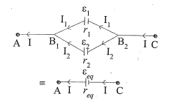
What is the parallel connection of cells ? Derive the formula for equivalent $e m f$ and equivalent internal resistance for parallel connection of cell.
Answer
→If the positive (or negative) terminal of two cells are connected to one point and their negative (or positive) terminal to another point,such connection of cells is called the parallel connection. →The figure shows a parallel combination of two cells, the emf of cells are $\varepsilon_1$ and $\varepsilon_2$ respectively and the internal resistances are $r_1$ and $r_2$ respectively. The currents leaving the positive terminals of the cells are $I_1$ and $I_2$ respectively. →These currents meet near point $B _1$ so the total current at point $B_1$ is $I=I_1+I_2$ →Let $V\left(B_1\right)$ and $V\left(B_2\right)$ be the potentials at $B_1$ and $B _2$. The potential diference across terminals of the first cell is $\begin{aligned} & V = V \left( B _1\right)- V \left( B _2\right)=\varepsilon_1- I _1 r_1 \\ \therefore & I _1 r_1=\varepsilon_1- V \\ \therefore & I _1=\frac{\varepsilon_1- V }{r_1} \end{aligned}$ →The potential difference across terminals of the second cell is $\begin{array}{rlrl} V & = V \left( B _1\right)- V \left( B _2\right)=\varepsilon_2- I _2 r_2 \\ \therefore & I _2 r_2 & =\varepsilon_2- V \\ & \therefore & I _2 & =\frac{\varepsilon_2- V }{r_2} \end{array}$ →But the total current is $I = I _1+ I _2$ →Putting the values from equation (1) and (2) in above equation : $\begin{array}{l} \therefore I =\frac{\varepsilon_1- V }{r_1}+\frac{\varepsilon_2- V }{r_2} \\ \therefore I =\frac{\varepsilon_1}{r_1}-\frac{ V }{r_1}+\frac{\varepsilon_2}{r_2}-\frac{ V }{r_2} \\ \therefore I =\frac{\varepsilon_1}{r_1}+\frac{\varepsilon_2}{r_2}- V \left(\frac{1}{r_1}+\frac{1}{r_2}\right) \\ \therefore V \left(\frac{1}{r_1}+\frac{1}{r_2}\right)=\frac{\varepsilon_1}{r_1}+\frac{\varepsilon_2}{r_2}- I \\ \therefore V \left(\frac{r_1+r_2}{r_1 r_2}\right)=\frac{\varepsilon_1 r_2+\varepsilon_2 r_1- I r_1 r_2}{r_1 r_2} \\ \therefore V \left(r_1+r_2\right)=\varepsilon_1 r_2+\varepsilon_2 r_1- I r_1 r_2 \\ \therefore V =\frac{\varepsilon_1 r_2+\varepsilon_2 r_1}{r_1+r_2}- I \left(\frac{r_1 r_2}{r_1+r_2}\right) \end{array}$ →Let the equivalent $e m f \varepsilon_{e q}$ and equivalent internal resistance $r_{e q}$ for this combination. $\therefore V =\varepsilon_{e q}- I r_{e q}$ by comparing equation (3) and (4) $\begin{aligned} \therefore \varepsilon_{e q} & =\frac{\varepsilon_1 r_2+\varepsilon_2 r_1}{r_1+r_2} \text { and } r_{e q}=\frac{r_1 r_2}{r_1+r_2} \\ \therefore \frac{\varepsilon_{e q}}{r_{e q}} & =\frac{\frac{\varepsilon_1 r_2+\varepsilon_2 r_1}{r_1+r_2}}{\frac{r_1 r_2}{r_1+r_2}}=\frac{\varepsilon_1 r_2+\varepsilon_2 r_1}{r_1 r_2}=\frac{\varepsilon_1}{r_1}+\frac{\varepsilon_2}{r_2} \end{aligned}$ →If there are $n$ cells of emf $\varepsilon_1, \varepsilon_2, \varepsilon_3 \ldots . \varepsilon_n$ and internal resistances $r_1, r_2, r_3 \ldots . r_n$ respectively are connected in parallel, the combination is equivalent to a single cell of emf $\varepsilon_{e q}$ and internal resistance $r_{e q}$. $\begin{array}{l} \therefore \frac{1}{r_{e q}}=\frac{1}{r_1}+\frac{1}{r_2}+\frac{1}{r_3}+\ldots+\frac{1}{r_n} \\ \therefore \frac{\varepsilon_{e q}}{r_{e q}}=\frac{\varepsilon_1}{r_1}+\frac{\varepsilon_2}{r_2}+\frac{\varepsilon_3}{r_3}+\ldots+\frac{\varepsilon_n}{r_n} \end{array}$
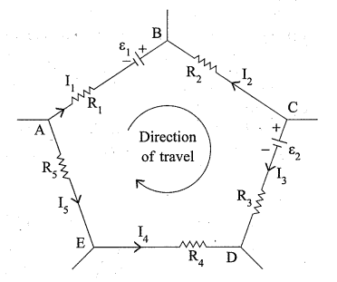
→Kirchhoff's loop rule : "The algebric sum of changes in potential around any closed loop involving resistors and cells in the loop is zero."
→Let us consider a closed path ABCDEA as shown in figure. →This circuit consists of resistors $R_1, R_2, R_3, R_4$, $R _5$ as well as batteries of $e m f s \varepsilon_1$ and $\varepsilon_2$ with negligible internal resistances.
Explain how resistance of conductor depends on the dimension of the conductor and derive its equation.
Answer
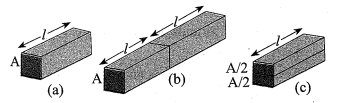
→A slab of conductor having length $l$ and cross sectional area A is shown in figure (a). →As shown in the figure (b), two similar blocks (slabs) are placed side by side so that the length of the combination is $2 l$ but the cross sectional area A remains the same. →If the current I is flowing through the combination, then the same current $I$ is flowing through the each of the slabs. →If V is the potential difference across the ends of the first slab then V is the potential difference across the ends of the second slab. →Thus, the potential difference (p.d.) across the ends of the combination equals to 2 V . →The resistance of the combination $\left( R _c\right)$ $R _c=\frac{2 V}{ I }=2 R$ →Thus, doubling the length of a conductor doubles the resistance. →So, resistance of a conductor is directly proportional to its length. (R $\propto l$ ) →As shown in figure (c), imagine dividing the slab into two by cutting it lengthwise so that the slab can be considered as a combination of two identical slabs of length $l$ having a cross sectional area of $\frac{ A }{2}$. →Suppose the potential differance across the slab is V . →The net current flowing through the slab is I, then the current flowing through each of the two half-slabs is $\frac{I}{2}$. →The resistance of each of the half-slabs is $R _1=\frac{ V }{\frac{ I }{2}}=\frac{2 V}{ I }=2 R$ →Thus, halving the area of the cross-section of a conductor doubles the resistance. →So, the resistance and the cross sectional area are inversely proportional to each other. $\left( R \propto \frac{1}{A}\right)$ →In general, the resistance of a conductor is inversely proportional to the cross- sectional area and directly proportional to length. $\therefore \quad R \alpha \frac{l}{A}$ $\therefore \quad R =\frac{ \rho l}{A}$ Where § is constant of proportionality, it is called the resistivity of material. →The magnitude of resistivity depends on the (1) type of material and (2) its temperature but not on its dimensions. The unit of the resistivity is $\Omega m$. → Using eq ${ }^{ n }$ (1) in ohm's law, $\begin{array}{l} V = IR \\ V =\frac{ Ig l}{A} \end{array}$
Explain emf, potential difference and internal resistance of cell and derive the relation between them. (or derive the relation between emf, potential difference and internal resistance of the cell.)
Answer
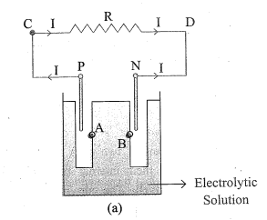
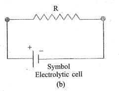
→The figure shows the electrolytic cell. Electrolytic cell is used to maintain a steady current in an electric circuit. →As shown in the figure, two electrodes, positive (P) and negative (N) are immersed in an electrolytic solution. →Because of being dipped in the solution, the electrodes exchange charges with the electrolyte. →The potential difference between the positive electrode and the adjacent point A is $V _{+}$and the potential difference between negative electrode to the adjacent point B is $- V _{-}$. →So, the potential difference between P and N is $V_{+}-\left(-V_{-}\right)=V_{+}+V_{-}$ →This potential difference is called the electromotive force (emf) of the cell and it is denoted by $\varepsilon$. $\therefore \varepsilon= V _{+}+ V _{-}>0$ →Definition of emf : The potential difference between two electrodes when no current is flowing through the cell is called the emf of the cell. →As shown in the figure, consider a resistor R connected across the cell and current I flows across R from C to D and current in electrolyte current flows from N to P . clearly, across the electrolyte →the same current flows through the electrolyte. The electrolyte through which a current flows has a finite resistance $r \&$ it is called the internal resistance. →Case I : $R =\infty$ (infinite) According to ohm's law $I =\frac{ V }{ R } \rightarrow I =0$ where V is the potential difference between P and N and it is called terminal voltage (or voltage) of the cell. →The potential difference between P and N , V (terminal voltage or voltage) $=$ Potential difference between P and A + Potential difference between A and B + Potential difference between B and N $\begin{aligned} V & = V _{+}+ V _{-} \\ \therefore V & =\varepsilon \end{aligned}$ →Thus, emf $\varepsilon$ is the potential difference between the positive and negative electrodes in an open circuit i.e when no current is flowing through the cell. →Case II : $R =$ Finite when $R$ is finite, electric current flows through the cell. In that case the potential difference between P and N is $\begin{aligned} V & = V _{+}+ V _{-}- I r \\ \therefore \quad V & =\varepsilon- I r \end{aligned}$ →The negative sign in the expression (Ir) for the potential difference between A and B . This is because the current I flows from B to A in the electrolyte.
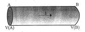
→ →As shown in figure, consider a conductor with end points A and B . In this conductor, current I is flowing from A to B . →The potential at A and B are $V ( A )$ and $V ( B )$ respectively. Since current is flowing from $A$ to $B, V(A)>V(B)$. →The potential difference across $A B$ $V = V ( A )- V ( B )>0$ →In time interval $\Delta t$, an amount of charge $\Delta Q =$ I $\Delta t$ flows from A to B . →The potential energy of the charge at $A$ is $\Delta Q . V ( A )$ and at B is $\Delta Q . V ( B )$. →Thus, change in potential energy. $\begin{array}{l} \Delta U =\text { final potential energy }- \text { initial potential } \\ \text { energy } \\ \therefore \Delta U=\Delta Q V(B)-\Delta Q V(A) \\ \therefore \Delta U=\Delta Q(V(B)-V(A)) \\ \therefore \Delta U=\Delta Q(-V) \quad\left(\because \text { from eq }{ }^{ n }(1)\right) \\ \therefore \Delta U=-\Delta Q . V \\ \therefore \Delta U =- IV \Delta t<0 \\ \end{array}$ →According to law of conservation of energy, $\begin{array}{l} \Delta K +\Delta U =0 \\ \therefore \Delta K=-\Delta U \\ \therefore \Delta K =-(- IV \Delta t) \quad\left(\because \text { from eq }^{ n }(2)\right) \\ \therefore \Delta K = IV \Delta t \text { (positive) } \\ \end{array}$ →Thus, from this equation it can be seen that a charge moving freely under the effect of an electric field acquires kinetic energy, it means kinetic energy increases. →But in reality, the charges in the conductor move with constant drift velocity, i.e. they gain no energy on an average. →This is because of the collisions with ions and atoms during the motion. During collisions, the energy gained by the charges is shared with the atoms, So the atoms vibrate more energetically, i.e. the conductor heats up. →Thus, kinetic energy of charge is converted in to heat energy. →Amount of energy dissipated as heat in the conductor during the time interval $\Delta t$ is $\Delta W = VI \Delta t$ →The energy dissipated per unit time is the dissipated power P . $\begin{array}{l} \therefore \quad P =\frac{\Delta W }{\Delta t} \\ \therefore P =\frac{ VI \Delta t}{\Delta t} \\ \therefore \quad P = VI \\ \end{array}$ →Using ohm's law $V = IR$ $\therefore P = I ^2 R$ →and also $P =\frac{ V ^2}{ R }$ can be derived. →The SI unit of electrical power is W (watt) OR J/s →Equations (5), (6) and (7) show dissipated power in conductor. (power loss or ohmic loss) →For example, when power is supplied to the coil of an electric bulb, this power is converted into heat and light.