Questions

[4 marks Questions]

🎯

Test yourself on this topic

15 questions · timed · auto-graded

Question 14 Marks
To understand about magnetic force acting on a current carrying conductor, when placed in an external magnetic field. Explain
Answer
⇒ Aim : To understand about magnetic force acting on a current carrying conductor, when placed in an external magnetic field.
⇒ Procedure with explanation :
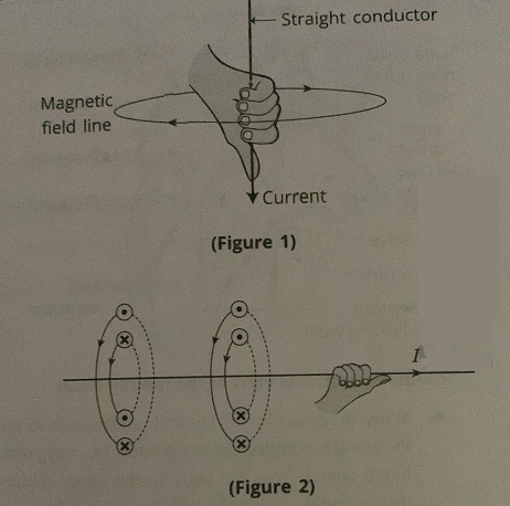
→ In the figure, $A B$ is light weight thin aluminium rod, placed between two magnetic poles of a horse shoe magnet, connected with battery, key and rheostat.
→ When the key $K$ is made closed, current passes through the rod from $B$ to $A$. We notice that rod gets displaced towards left.
Image
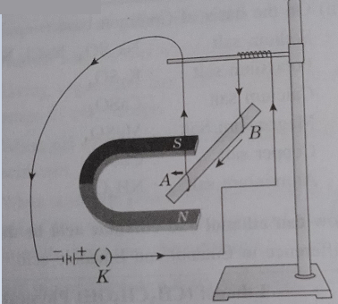
→ Now, after reversing the battery termmais, if above procedure is repeated then direction of current gets reversed. At this time, we notice that rod gets displaced towards right.
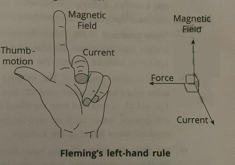
→ Conclusion : When a current carrying conductor is placed in some external magnetic field at an angle $0^{\circ}<\theta<180^{\circ}$, it experiences a magnetic force. Where direction of current passing through the conductor is reversed, direction of this magnetic force also gets reversed.
View full question & answer
Question 24 Marks
Explain in brief about Fleming's left hand rule.
Answer
Fleming's left hand rule is used to find direction of magnetic force acting on a current carrying straight conductor, when placed perpendicular to external magnetic field.
Image
→ As shown above, stretch left hand palm such that first finger (forefinger), second finger (middle finger) and thumb remain mutually perpendicular. At this time, if first finger points in the direction of magnetic field and second finger points in the direction of electric current then the thumb indicates direction of magnetic force acting on current carrying straight wire.
View full question & answer
Question 34 Marks
$(1)$ Mention in brief about "Right Hand Thumb Rule"
$(2)$ Explain in brief about Fleming's left hand rule.
Answer
(1) "Right Hand Thumb Rule" is used to find how magnetic field lines encircle around current carrying straight conducting wire.
Image
→ Right Hand Thumb Rule : Just imagine that you are holding a current carrying straight conducting wire with the help of your right hand palm such that thumb points in the direction of current. The circular magnetic field lines take the turn around the wire in the same manner as the fingers take the turn around the wire.
(2) Fleming's left hand rule is used to find direction of magnetic force acting on a current carrying straight conductor, when placed perpendicular to external magnetic field.
Image
→ "As shown above, stretch left hand palm such that first finger (forefinger), second finger (middle finger) and thumb remain mutually perpendicular. At this time, if first finger points in the direction of magnetic field and second finger points in the direction of electric current then the thumb indicates direction of magnetic force acting on current carrying straight wire.
View full question & answer
Question 44 Marks
What is called a solenoid ? Describe about magnetic field of a current carrying solenoid.
Answer
Image
→ As shown in the figure, solenoid is a helical coil having closely wound circular turns of insulated conducting wire (usually copper wire). The region inside the solenoid is called "core". The core of a solenoid is either air or some magnetic material.
Image
→ When electric current is passed through solenoid (i.e. through its windings), we get magnetic field around it which is quite analogous (similar) to that around a bar magnet. Hence, we can say that a current carrying solenoid acts like a bar magnet.
→ When length of a solenoid is extremely large as compared to radius of its cross - section, we consider it as a long solenoid.
→ When current is passed through a long solenoid, majority magnetic field is produced only inside it. Hence outside such solenoid, magnetic field is almost zero.
→ For extremely long current carrying solenoid, magnetic field exist inside it which is parallel to axis and uniform. Here magnetic field lines are parallel and equidistant from each other.
View full question & answer
Question 54 Marks
To study the pattern of magnetic field lines around a straight current carrying wire.
Answer
Image
→ As shown in figure $1$, consider a straight thick wire, passed through the centre of big size square shaped card board.
→ Now connect a $12 V$ battery, variable resistance (in the form of rheostat), an ammeter with a range of $0$ to $5 A$ with above wire as shown in figure $1$ (keeping wire $X Y$ vertical)
→ Now, sprinkle iron filings on above card board uniformly around the wire.
→ " Now, when key is closed, current starts passing through the vertical wire from $X$ to $Y$.
→ Now tap the card board gently few times. We notice that iron filings get aligned in the form of concentric circles.
→ These circles represent circular magnetic field lines. When a compass is placed at any point on any of these circles, its north pole points along the tangent to that circle at that point, which gives direction of magnetic field at that point.
→ "When current in the wire increases, deflection of needle in the compass increases proportionally. But when distance of compass from the wire is increased, deflection of needle in the compass decreases.
→ As shown in figure $2$, when direction of current passing through the wire is reversed, north pole of needle in the compass points in opposite direction.
•Conclusion :
→ If strength of magnetic field is $B$, current through the wire is $I$, radius of circular field line is $r$ then we conclude that :
(i) $B \propto I$
(ii) $B \propto \frac{1}{r}$
→ Also, when direction of current is reversed, direction of magnetic field also gets reversed.
View full question & answer
Question 64 Marks
Explain electrical energy and derive its formula. Obtain Joule's law of heating.
Answer
  • A metallic conductor (or a resistance wire) offers resistance to the flow of current, so work must be done by the current-source for a continuous flow of electric current through a conductor.

[A steady current in a purely resistive electric circuit]
  • Consider a current $l$ flowing through a resistor (or conductor) of resistance $R.$ Let $V$ be the potential difference across the resistor (see figure).
  • Let t be the time-interval during which a charge $Q$ flows through the resistor (conductor).
  • The work done by the current source in moving charge $Q$ through a potential difference $V$ is $VQ.$
  • Therefore, the current source must supply energy to the circuit equal to $VQ$ in time t.
  • Thus, energy spent by the source or the work done by the source,
  • W = VQ
  • $W = VQ$
  • $V ( It )\left(\because I =\frac{ Q }{t}\right)$
  • $=( IR )( It )(\text { By the Ohm's law } V = IR )$
  • $W = I ^2 Rt \ldots \ldots . . .(12.15)$
  • This electrical energy gets dissipated as heat in the resistor. Thus for current $I$, the amount of heat $H$ generated (produced) in time- interval t is
  • $H=I^2 R t$
  • This is known as the Joule's law of heating.
  • The $SI$ unit of electrical energy and heat energy is the joule $(J)$. Its other units are $(Ws)$ and kilowatt-hour $(kWh)$ or unit (commercial unit for electrical energy).
View full question & answer
Question 74 Marks
Derive the formula of the heat energy produced in the conductor because of electric current flows in it for the fixed time-interval ‘t’. Give its unit.
Answer
  • A metallic conductor (or a resistance wire) offers resistance to the flow of current, so work must be done by the current-source for a continuous flow of electric current through a conductor.

[A steady current in a purely resistive electric circuit]
  • Consider a current $I$ flowing through a resistor (or conductor) of resistance $R$. Let $V$ be the potential difference across the resistor (see figure).
  • Let t be the time-interval during which a charge $Q$ flows through the resistor (conductor).
  • The work done by the current source in moving charge $Q$ through a potential difference $V$ is $VQ.$
  • Therefore, the current source must supply energy to the circuit equal to $VQ$ in time t.
  • Thus, energy spent by the source or the work done by the source,
  • $W = VQ$
  • $V \left( I _{ t )}\left(\because I _{=}{ }^{\underline{Q}}{ }_t\right)\right.$
  • $=( IR ) \text { (It) (By the Ohm's law } V = IR )$
  • $W = I _2 Rt$
  • This electrical energy gets dissipated as heat in the resistor. Thus for current $I$, the amount of heat $H$ generated (produced) in time- interval t is
  • $H={ }^{I_2} R t …….(12.16)$
  • This is known as the Joule's law of heating.
  • The $SI$ unit of electrical energy and heat energy is the joule $(J)$. Its other units are $(Ws)$ and kilowatt-hour $(kWh)$ or unit (commercial unit for electrical energy).
View full question & answer
Question 84 Marks
To verify Ohm's law.
Answer
 
  • Procedure:
  • Set up a circuit as shown in figure $12.3$, consisting of a Nichrome wire $XY$ of length say $0.5$ nm, an ammeter, a voltmeter and four cells of $1.5V$ each.
  • First use only one cell as the source in the circuit.
  • Note the reading of ammeter $I$, for the current and reading of the voltmeter $V$ for the potential difference across the Nichrome wire $XY$ in the circuit.
  • Tabulate them in the Table given.
  • Next connect two cells in the circuit and note the respective readings of the ammeter and voltmeter for the values of current through the Nichrome wire and potential difference across the Nichrome wire.
  • Repeat the above steps using three cells and then four cells in the circuit separately.
  • Calculate the ratio $V$ to $I$ for each pair of potential difference $V$ and current $I$.
  • Observation table:
Sr. NO. Number of cells used in the circuit Potential difference across the Nichrome wire $V$(volt) Current through the Nichrome wire $I$(ampere) $\frac{V}{I}$(volt/ampere)
$1.$ $1$ $1.5$ $0.1$ $15$
$2.$ $2$ $3$ $0.2$ $15$
$3.$ $3$ $4.5$ $0.3$ $15$
$4.$ $`$ $6$ $0.4$ $15$
  • Plot a graph between $V$ and $I$ and observe the nature of the graph.
  • (Take the voltage $(V)$ on X-axis and the current $(I)$ on Y-axis. Draw the graph of $I-V$ taking proper scale.)

$[I \rightarrow V$ graph $]$
  • Observation:
  • When $V$ increases $I$ also increases linearly, i.e., $I \propto V$. The ratio $V / I$ is found to be (approximately) the same, i.e., $15 V/A.$
  • The graph between $V$ and $I$ is a straight line passing through the origin
  • Conclusion:
  • The electric current flowing through a metallic wire is directly proportional to the potential difference across its ends ($I \propto V$) and $V/I$ is a constant ratio in particular case.
View full question & answer
Question 94 Marks
To find the relationship between potential difference $(V)$ and current $(I)$.
Answer
  • Procedure:
  • Set up a circuit as shown in figure $12.3$, consisting of a Nichrome wire $XY$ of length say $0.5$ nm, an ammeter, a voltmeter and four cells of $1.5V$ each.
  • First use only one cell as the source in the circuit.
  • Note the reading of ammeter $I$, for the current and reading of the voltmeter $V$ for the potential difference across the Nichrome wire $XY$ in the circuit.
  • Tabulate them in the Table given.
  • Next connect two cells in the circuit and note the respective readings of the ammeter and voltmeter for the values of current through the Nichrome wire and potential difference across the Nichrome wire.
  • Repeat the above steps using three cells and then four cells in the circuit separately.
  • Calculate the ratio $V$ to $I$ for each pair of potential difference $V$ and current $I$.
  • Observation table:
Sr. NO. Number of cells used in the circuit Potential difference across the Nichrome wire $V$(volt) Current through the Nichrome wire $I$(ampere) $\frac{V}{I}$ (volt/ampere)
1. 1 1.5 0.1 15
2. 2 3 0.2 15
3. 3 4.5 0.3 15
4. ` 6 0.4 15
  • Plot a graph between $V$ and $I$ and observe the nature of the graph.
  • (Take the voltage ($V$) on X-axis and the current ($I$) on Y-axis. Draw the graph of $I$-$V$ taking proper scale.)

[$I \rightarrow V$ graph]
  • Observation:
  • When $V$ increases $I$ also increases linearly, i.e., $I \propto V$. The ratio $V$/$I$ is found to be (approximately) the same, i.e., $15 V/A$.
  • The graph between $V$ and $I$ is a straight line passing through the origin
  • Conclusion:
  • The electric current flowing through a metallic wire is directly proportional to the potential difference across its ends ($I \propto V$) and V/I is a constant ratio in particular case.
View full question & answer
Question 104 Marks
What is electric energy? What is its commercial (or practical) unit? Define it.
Answer
  • “Electric energy is the amount of energy consumed in an electric circuit in a given time $t$.”
  • The energy consumed not only depends upon the electric power of the appliance but also upon the time for which the power is maintained.
  • If a power $P$ (watt) is maintained for time $t$ (second), then the work done or electric energy consumed is
  • $W$ (joule) = $P$ (watt) × $t$ (second)
OR
  • Electrical energy $W$ = Electric, power $P$ × time $t$ …….$(12.21)$
  • But the unit ‘watt’ is very small.
  • Therefore in actual practice we use a much larger unit called ‘kilowatt’ which is equal to $1000$ watt.
  • Since electrical energy is the product of power and time, the unit of electric energy is, therefore, watt hour $(Wh)$.
  • “One watt hour is the energy consumed when $1$ watt power is used for $1$ hour.”
  • The commercial (or practical) unit of electric energy is kilowatt hour $(kWh)$, commonly known as ‘unit’.
  • $1$ kWh = $1$ kilowatt × $1$ hour
  • $= 1000$ watt × $3600$ second
  • $= 3.6 × 10^6$ watt second
  • $= 3.6 × 10^6$ joule (J)
View full question & answer
Question 114 Marks
What is meant by electric power? Obtain a formula for it. State units of electric power.
Answer
  • Power is the rate of doing work.
  • When work is done, an equal amount of electric energy is consumed. Hence,
  • “The rate at which electric energy is consumed or dissipated is called electric power.”
  • IF W is the amount of electric energy consumed in a circuit in time t (second), then electric power is given by
  • P = $\frac{W}{t}$ .... (12.17)
  • But, the electric energy supplied by a current-source in time t is
  • W = VQ
  • P = $\frac{W Q}{t}$
  • Now, current $I$= $\frac{Q}{t}$
  • ∴ P = VI ..... (12.18)
  • From Ohm's law V = IR
  • So, P = (IR) I
  • ∴ P = $I^2R ..... (12.19)$
  • Again from the Ohm's law $I$ = $\frac{V}{R}$
  • So, P = $\left(\frac{V}{R}\right)^2$R …..(12.20)
  • The $SI$ unit of electric power is the watt (W).
  • Hence, from equation (12.18),
  • watt = volt × ampere
  • Thus, 1 W = 1 volt × 1 ampere = 1 VA
  • Definition of the $SI$ unit of power:
  • Electric power consumed by a device is said to be 1 w if it carries 1A of current when operated at a potential difference of 1 V.
OR
  • Electric power of an electric device is 1 watt if it consumes 1 joule of electric energy in 1 second.
View full question & answer
Question 124 Marks
Explain the parallel combination of resistors and derive the formula of equivalent resistance.
Answer
  • Two or more than two resistors are said to be connected in parallel if one end of each resistor is connected to one point and the other end is connected to another point so that more than one paths are available for the current to flow and potential difference across each resistor is the same and is equal to the applied potential difference between the two common points.
  • Three resistors with resistances, $R_1, R_2$ and $R_3$ are connected in parallel between points $A$ and $B$ as shown in the figure(a).
  • Here, the current $I$ gets divided at point A amongst three resistors as shown in the figure.
  • Let $I_1$, $I_2$ and $I_3$ be the currents flowing through the resistors with resistances $R_1,R_2$ and $R_3$ respectively.
  • $\therefore$ $I=I_1+I_2+I_3 \ldots \ldots(12.12)$
  • In a parallel combination of resistors, the potential difference across every resistor is equal to the potential difference V of the battery.
  • According to Ohm's law,
  • $l_1$ =$\frac{\mathrm{V}}{\mathrm{R}_{\mathrm{1}}}$, $l_2$ = $\frac{\mathrm{V}}{\mathrm{R}_{\mathrm{2}}}$ and $l_3$ = $\frac{\mathrm{V}}{\mathrm{R}_{\mathrm{3}}}$
  • $\therefore$ $l_1$ = $\frac{\mathrm{V}}{\mathrm{R}_{\mathrm{1}}}$ $\frac{\mathrm{V}}{\mathrm{R}_{\mathrm{2}}}$ + $\frac{\mathrm{V}}{\mathrm{R}_{\mathrm{3}}}$ ...... $(12.13)$
  • Now, if a resistor with resistance $R_p$, instead of three resistors with resistances $R_1,R_2$ and $R_3$, is connected in the circuit such that the current flowing through the circuit remains the same as $I$ then $R_p$ is called the equivalent resistance of the circuit [see figure(b)].
  • I = $\frac{\mathrm{V}}{\mathrm{R}_{\mathrm{p}}}$ ... ... $(12.14)$
  • From equation $(12.13)$,
  • $\frac{\mathrm{V}}{\mathrm{R}_{\mathrm{p}}}$ = $\frac{\mathrm{V}}{\mathrm{R}_{\mathrm{1}}}$+ $\frac{\mathrm{V}}{\mathrm{R}_{\mathrm{2}}}$ + $\frac{\mathrm{V}}{\mathrm{R}_{\mathrm{3}}}$
  • $\therefore$ $\frac{\mathrm{V}}{\mathrm{R}_{\mathrm{p}}}$ = $\frac{\mathrm{V}}{\mathrm{R}_{\mathrm{1}}}$ +$\frac{\mathrm{V}}{\mathrm{R}_{\mathrm{2}}}$ + $\frac{\mathrm{V}}{\mathrm{R}_{\mathrm{3}}}$
  • Thus, in a parallel combination of resistors, the sum of the reciprocals of the individual resistances is equal to the reciprocal of the equivalent resistance $R_p$. $R_p$ is less than any of the individual resistances in the circuit.
View full question & answer
Question 134 Marks
Explain the series combination of resistors and derive the formula of equivalent resistance.
Answer
  • Two or more than two resistors are said to be connected in series, if they are joined end to end and the same (i.e., total) current flows through each one of them when a potential difference is applied across the combination.
  • In figure $(a)$, three resistors with resistance $R_1, R_2$ and $R_3$ are connected in series across the points $A$ and $B$. Here, current ($I$) flowing through each of the resistors $R_1, R_2$ and $R_3$ is the same, but the total potential difference (p.d.) of the battery $V$ is divided according to the resistances between the two ends of the respective resistors.
  • If the potential difference (p.d.) across $R_1, R_2$ and $R_3$ are $V_1, V_2$ and $V_3$ respectively, then
  • $V = V_1, V_2$ and $V_3 ...... (12.8)$
  • Now, if one resistor with resistance $R_s$ , instead of these three resistors with resistances $R_1, R_2$ and $R_3$ is connected in the circuit in such a way that the current flowing through the circuit remains the same as $I$, then $R_s$ is the resistance of the series combination.
  • It is also called equivalent resistance of the combination [figure $12.11 (b)$].
  • Now, applying Ohm's law, $V = IR_s$ ... ... $(12.9)$
  • From equation $(12.8)$ and $(12.9)$,
  • $IR$ = $V_1, V_2$ and $V_3$ ... ... $(12.10)$
  • On applying Ohm's law to the three resistors separately, we have
  • $V_1$ = $IR_1$
  • $V_2$ = $IR_2$
  • $V_3$ = $IR_3$
  • ∴$IR_s$ = $IR_1+IR_2$ + $IR_3$
  • ∴ $R_s$ = $R_1, R_2$ and $R_3$ ... ... $(12.11)$
  • Thus, the equivalent resistance $R_s$ of the series combination is equal to the sum of the individual resistances and is thus greater than any of the individual resistances.
View full question & answer
Question 144 Marks
Define electric potential difference. State the formula for it. Name and define the $SI$ unit of potential difference.
Answer
  • Definition of electric potential difference:
  • The electric potential difference $(p.d.)$ between any two points $A$ and $B$ in an electric field is the work done to move a unit positive charge $(+ 1 C)$ from one point $A$ to the another point $B$ against the electric force due to the electric field.
  • Potential difference $(V)$ between two points
  • $=\frac{\text { Work done }( W )}{\text { Charge }( Q )}$
  • If potential at point A is $V_A$ and that at point B is $V_B$, electric potential difference between points A and B is
  • $Potential at{\text { Final Point B }}-\frac{\text { Potential at }}{\text { Initial Point } A}=\frac{W}{Q}$
  • $i.e., V_B-V_A=\frac{W}{Q} \ldots \ldots .(12.3)$
  • If $V _{ B }- V _{ A }$ is denoted by $V , V =\frac{W}{Q}$
  • Electric potential difference $(p.d.)$ is also known as voltage.
  • The SI unit of p.d. is volt or joule / coulomb.
  • Definition of the volt:
  • The potential difference between two points in an electric field is said to be $1$ volt if $1$ J of work is done to move a
  • charge of $1 \ C$ from one point to another point.
  • $\left(1 V=\frac{1 J}{1 C }\right)$
View full question & answer
Question 154 Marks
Give the deference : Series combination of resistors and Parallel combination of resistors.
Answer
Series combination of resistors Parallel combination of resistors
$1$. In a series combination of resistors, the resistors are connected across two points in the circuit such that the current flowing through each resistor is the same and only one path is available for the current to flow. $1$. In a parallel combination of resistors, the resistors are connected across two points in the circuit such that the voltage drop across two ends of each resistor remains the same and more than one path are available for the current to flow.
$2$. In this case, the total voltage drop is equal to the sum of the voltage drops across each resistor. $2$. In this case, the total current flowing through the circuit is equal to the sum of the currents flowing through each resistor.
$૩$. The equivalent resistance of a series combination of resistors is equal to the sum of the resistances of the individual resistors. $3$. The reciprocal of the equivalent resistance of a parallel combination of resistors is equal to the sum of the reciprocal of the resistances of the individual resistors.
$4$. In this case, the equivalent resistance is greater than the largest of all the individual resistances. $4$. In this case, the equivalent resistance is smaller than the smallest of all the individual resistances.
$5$. This combination is used in order to increase the resistance of the circuit. $5$. This combination is used in order to decrease the resistance of the circuit.
$6$. In this case, the total current in the circuit decreases. $6$. In this case, the total current in the circuit increases.
View full question & answer
[4 marks Questions] - Science STD 10 Questions - Vidyadip