A battery of $e.m.f.$ $10\, V$ and internal resistance $0.5\, ohm$ is connected across a variable resistance $R$. The value of $R$ for which the power delivered in it is maximum is given by ......... $ohm$
AIPMT 1992, Easy


Download our appand get started for free
Experience the future of education. Simply download our apps or reach out to us for more information. Let's shape the future of learning together!No signup needed.*
Similar Questions
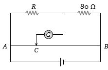
- 1$AB$ is a wire of uniform resistance. The galvanometer $G$ shows no current when the length $AC = 20\,cm$ and $CB = 80\, cm$. The resistance $R$ is equal to .............. $\Omega $View Solution
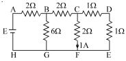
- 2The figure shows a network of resistors and $a$ battery. If $1\,A$ current flowsthrough the branch $CF$, then answer the following questions The $\mathrm{emf}$ $E$ of the battery is If a zero resistance wire is connected in parallel to branch $CF$ ............... $V$View Solution
- 3For a cell of $e.m.f.$ $2\,V$, a balance is obtained for $50\, cm$ of the potentiometer wire. If the cell is shunted by a $2\,\Omega $ resistor and the balance is obtained across $40\, cm$ of the wire, then the internal resistance of the cell is ............. $\Omega $View Solution
- 4In a Wheatstone’s bridge all the four arms have equal resistance $R$. If the resistance of the galvanometer arm is also $R$, the equivalent resistance of the combination as seen by the battery isView Solution
- 5A beam contains $2 \times 10^8$ doubly charged positive ions per cubic centimeter, all of which are moving with a speed of $10^5 \,m/s$. The current density is ............. $A/m^2$View Solution
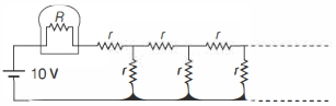
- 6A light bulb of resistance $R=16 \,\Omega$ is attached in series with an infinite resistor network with identical resistances $r$ as shown below. A $10 \,V$ battery drives current in the circuit. ............. $\Omega$ the value of $r$ such that the bulb dissipates about $1 \,W$ of power.View Solution
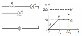
- 7In the circuit shown below (on the left) the resistance and the emf source are both variable. The graph of seven readings of the voltmeter and the ammeter ( $V$ and $I$, respectively) for different settings of resistance and the emf, taken at equal intervals of time $\Delta t$, are shown below (on the right) by the dots connected by the curve $E F G H$. Consider the internal resistance of the battery to be negligible and the voltmeter an ammeter to be ideal devices. (Take, $R_0 \equiv \frac{V_0}{I_0}$ ).View Solution
Then, the plot of the resistance as a function of time corresponding to the curve $E F G H$ is given by
- 8Potential difference across $A B$ in the network shown is .........View Solution
- 9Suppose the drift velocity $v_d$ in a material varied with the applied electric field $E$ as ${v_d}\, \propto \,\sqrt E $ .Then $V - I$ graph for a wire made of such a material is best given byView Solution
- 10View SolutionAssertion : Long distance power transmission is done at high voltage.
Reason : At high voltage supply power losses are less.