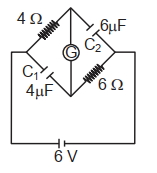
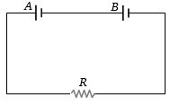
A galvanometer $(G)$ $\Omega$ of 2 risistance is connected in the givn circuit the raito of charge in $C_1$ and $C_2$ is:
JEE MAIN 2024, Diffcult


Download our appand get started for free
Experience the future of education. Simply download our apps or reach out to us for more information. Let's shape the future of learning together!No signup needed.*
Similar Questions
- 1View SolutionThe material of fuse wire should have
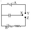
- 2In the circuit shown the cells are ideal and of equal emfs, the capacitance of the capacitor is $C$ and the resistance of the resistor is $R. X$ is first joined to $Y$ and then to $Z$. After a long time, the total heat produced in the resistor will beView Solution
- 3Two batteries with e.m.f $12\ V$ and $13\ V$ are connected in parallel across a load resistor of $10\,\Omega$ . The internal resistances of the two batteries are $1\,\Omega$ and $2\,\Omega$ respectively. The voltage across the load lies betweenView Solution
- 4The current $I$ drawn from the $5$ volt source will be ............... $A$View Solution

- 5View SolutionThe temperature at which thermal electric power of a thermo couple becomes zero is called
- 6The electric field $E$, current density $J$ and conductivity $\sigma$ of a conductor are related asView Solution
- 7Two batteries $A$ and $B$ each of $e.m.f.$ $2\, V$ are connected in series to an external resistance $R = 1 \,ohm$. If the internal resistance of battery $A$ is $1.9\, ohms$ and that of $B$ is $0.9\, ohm$, what is the potential difference between the terminals of battery $A$ ............. $V$View Solution
- 8A potentiometer has uniform potential gradient across it. Two cells connected in series $(i)$ to support each other and $(ii)$ to oppose each other are balanced over $6\,m$ and $2\,m$ respectively on the potentiometer wire. The $e.m.f.$’s of the cells are in the ratio ofView Solution
- 9In the circuit shown, the thermal power dissipated in $R_1$ is $P$. The thermal power dissipated in $R_2$ isView Solution
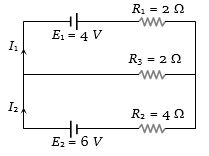
- 10In the circuit shown below $E_1 = 4.0 \,V, R_1= 2 \Omega, E_2 = 6.0 \,V, R_2 = 4 \,\Omega$ and $R_3 = 2 \,\Omega$. The current $I_1$ is ..................... $A$View Solution