A series combination of two resistors $1\,\Omega $ each is connected to a $12\,V$ battery of internal resistance $0.4\,\Omega $. The current flowing through it will be ............... $A$
Easy
Download our app for free and get started
(b) $i = \frac{{12}}{{(1 + 1) + 0.4}} = 5\,A.$

Download our appand get started for free
Experience the future of education. Simply download our apps or reach out to us for more information. Let's shape the future of learning together!No signup needed.*
Similar Questions
- 1If two wires having resistance $R$ and $2R$. Both joined in series and in parallel then ratio of heat generated in this situation, applying the same voltage,View Solution
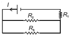
- 2Refer to the circuit shown. What will be the total power dissipation in the circuit if $P$ is the power dissipated in $R_1$ ? It is given that $R_2=4 R_1$ and $R_3=12 R_1$ are .......... $P$View Solution
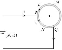
- 3A wire of resistance $10$ $\Omega$ is bent to form a circle. $P$ and $Q$ are points on the circumference of the circle dividing it into a quadrant and are connected to a Battery of $3\, V$ and internal resistance $1$ $\Omega$ as shown in the figure. The currents in the two parts of the circle areView Solution
- 4View SolutionThe material of wire of potentiometer is
- 5A wire has a resistance of $12\, ohm$. It is bent in the form of equilateral triangle. The effective resistance between any two corners of the triangle isView Solution
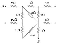
- 6What is the equivalent resistance between the points $A$ and $B$ of the network .................. $\Omega$View Solution
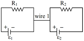
- 7In the circuit, wire $1$ is of negligible resistance. Then,View Solution
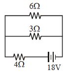
- 8The total power dissipated (in $watt$ ) in the circuit shown isView Solution
- 9The resistance of a coil is $4.2\, \Omega$ at $100\,^o C$ and the temperature coefficient of resistance of its material is $ 0.004\,^o C$. Its resistance at $0\,^o C$ is ............. $\Omega$View Solution
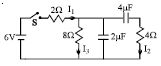
- 10In the circuit shown in the figure, the switch $S$ is initially open and the capacitor is initially uncharged. $ I_1, I_2$ and $I_3$ represent the current in the resistance $2\,\Omega , 4\,\Omega $ and $8\,\Omega$ respectively.View Solution