A wire of a certain material is stretched slowly by ten percent. Its new resistance and specific resistance become respectively
AIPMT 2008, Medium


Download our appand get started for free
Experience the future of education. Simply download our apps or reach out to us for more information. Let's shape the future of learning together!No signup needed.*
Similar Questions
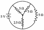
- 1The total current supplied to the circuit as shown in figure by the $5 V$ battery is $A$View Solution
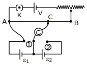
- 2In the given potentiometer circuit arrangement, the balancing length ${AC}$ is measured to be $250$ ${cm}$. When the galvanometer connection is shifted from point $(1)$ to point $(2)$ in the given diagram, the balancing length becomes $400\, {cm}$. The ratio of the emf of two cells, $\frac{\varepsilon_{1}}{\varepsilon_{2}}$ is -View Solution
- 3The resistance of the series combination of two resistance is $S$. When they are joined in parallel the total resistance is $P$. If $S = nP$, then the minimum possible value of $n$ isView Solution
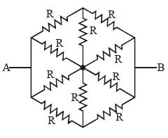
- 4Find out equivalent resistance between $A$ and $B$View Solution
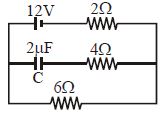
- 5Find the charge on the capacitor $C$ in the following circuit ............. $\mu C$View Solution
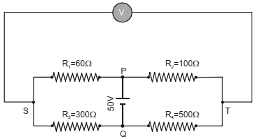
- 6In the balanced condition, the values of the resistances of the four arms of a Wheatstone bridge are shown in the figure below. The resistance $R_3$ has temperature coefficient $0.0004{ }^{\circ} C ^{-1}$. If the temperature of $R_3$ is increased by $100{ }^{\circ} C$, the voltage developed between $S$ and $T$ will be. . . . . . . volt.View Solution
- 7A cell of $emf$ $E$ and internal resistance $r$ is connected in series with an external resistacne $nr.$ Then, the ratio of the terminal potential difference to $emf$ isView Solution
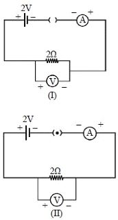
- 8For the circuits shown in figures $I$ and $II$, the voltmeter reading would beView Solution
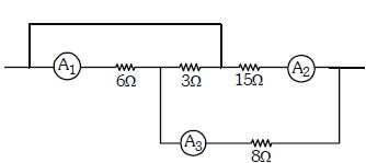
- 9A part of circuit is shown in figure. All the ammeters are ideal. If reading of ammeter $A_1$ is $1.0\ A$ , thenView Solution
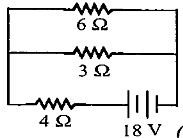
- 10The total power dissipated in watt in the circuit shown here is ............. $W$View Solution