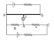
Circuit for the measurement of resistance by potentiometer is shown. The galvanometer is first connected at point $A$ and zero deflection is observed at length $P J = 10\ cm$ . In second case it is connected at point $C$ and zero deflection is observed at a length $30\ cm$ from $P$ . Then the unknown resistance $X$ is
Medium
Download our app for free and get started
In potentiometer wire potential difference is directly proportional to length
Let potential drop unit length a potentiometer wire be $\mathrm{K}.$
For zero deflection the current will flow independently in two circles
$\mathrm{IR}=\mathrm{K} \times 10$ ............$(1)$
$\mathrm{IR}+\mathrm{IX}=\mathrm{K} \times 30$ .........$(2)$
$(2)-(1)$
$\Rightarrow \mathrm{IX}-\mathrm{k} \times 20$ ........$(3)$
Divide $(1)$ and $(2)$
$\frac{\mathrm{R}}{\mathrm{X}}=\frac{1}{2} \Rightarrow \mathrm{x}=2 \mathrm{\,R}$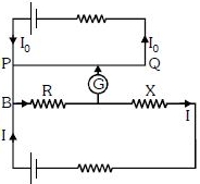

Download our appand get started for free
Experience the future of education. Simply download our apps or reach out to us for more information. Let's shape the future of learning together!No signup needed.*
Similar Questions
- 1Carbon resistor has resistance specified by three bands having colour red, yellow and black. If this resistor is cut into two pieces of equal length then the new colour code of each one will be (Neglect tolerance of $4^{th}$ band)View Solution
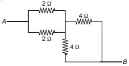
- 2Effective resistance across $A B$ in the network shown in .......... $\Omega$View Solution
- 3In the circuit diagram shown in figure given below, the current flowing through resistance $3\, \Omega$ is $\frac{ x }{3}\,A$. The value of $x$ is $...........$View Solution
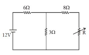
- 4The maximum power delivered to resistance $R$ is ............... $W$View Solution
- 5View SolutionThe length of the wire is doubled. Its conductance will be
- 6There are a large number of cells available, each marked $(6 \,V , 0.5 \,\Omega)$ to be used to supply current to a device of resistance $0.75 \,\Omega$, requiring $24 \,A$ current. How should the cells be arranged, so that power is transmitted to the load using minimum number of cells?View Solution
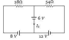
- 7Consider the circuit shown in the figure. The current ${I_3}$ is equal toView Solution
- 8The resistances of the four arms $P, Q, R$ and $S$ in a Wheatstone's bridge are $10\,ohm$, $30\,ohm$, $30\,ohm$ and $90\,ohm$, respectively. The e.m.f. and internal resistance of the cell are $7\,volt$ and $5\,ohm$ respectively. If the galvanometer resistance is $50\,ohm$, the current drawn from the cell will be ............... $A$View Solution
- 9Three resistances $4\,\Omega $ each of are connected in the form of an equilateral triangle. The effective resistance between two corners isView Solution
- 10Following figures show different combinations of identical bulb$(s)$ connected to identical battery$(ies)$. Which option is correct regarding the total power dissipated in the circuit?View Solution