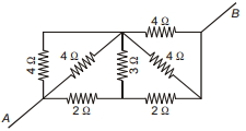
In a potentiometer circuit there is a cell of $e.m.f.$ $2\, volt$, a resistance of $5\, ohm$ and a wire of uniform thickness of length $1000\, cm$ and resistance $15\, ohm$. The potential gradient in the wire is
Medium


Download our appand get started for free
Experience the future of education. Simply download our apps or reach out to us for more information. Let's shape the future of learning together!No signup needed.*
Similar Questions
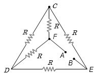
- 1Five equal resistances each of resistance $R$ are connected as shown in the figure. A battery of $V\, volts$ is connected between $A$ and $B$. The current flowing in $AFCEB$ will beView Solution
- 2In a conductor, if the number of conduction electrons per unit volume is $8.5 \times 10^{28}\, m^{-3}$ and mean free time is $25\,fs$ (femto second), its approximate resistivity is $\left( {{m_e} = 9.1 \times {{10}^{ - 31}}\,kg} \right)$View Solution
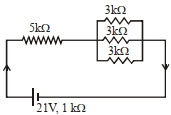
- 3In the figure given, the electric current flowing through the $5\, k \Omega$ resistor is $'x' mA.$View Solution
The value of $x$ to the nearest integer is .........
- 4The resistance of a wire is $R$. It is bent at the middle by $180^o$ and both the ends are twisted together to make a shorter wire. The resistance of the new wire isView Solution
- 5View SolutionThe net resistance of a voltmeter should be large to ensure that
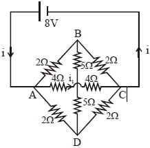
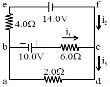
- 6The value of current $i_{1}$ flowing from $A$ to $C$ in the circuit diagram is$.......A$View Solution
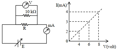
- 7To determine the resistance ($R$) of a wire, a circuit is designed below, The $V-I$ characteristic curve for this circuit is plotted for the voltmeter and the ammeter readings as shown in figure. The value of $\mathrm{R}$ is . . . . . . .$\Omega$View Solution
- 8View SolutionAssertion : Bending a wire does not effect electrical resistance.
Reason : Resistance of wire is proportional ot resistivity of material.
- 9Find the value of current $i_1$ for the circuit shown in figure :- ............ $A$View Solution
- 10Resistance across $A B$ as shown in figure is ............. $\Omega$View Solution