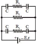
In the circuit diagram of figure, $E = 5\, volt, r = 1\, \Omega ,$$ R_2 = 4\, \Omega , R_1 = R_3 = 1 \Omega$ and $C = 3\, μF.$ Then the magnitude of the charge on each capacitor plate is......$\mu C$
Medium
Download our app for free and get started
$6 \,\mu \mathrm{C},$ Hint : the $p.d$ across $\mathrm{R}_{2}$ is $4$ $volt.$ The total charge in the two parallel arms is $12\, \mu C$.
Thus in each row,
$q=6\, \mu C.$

Download our appand get started for free
Experience the future of education. Simply download our apps or reach out to us for more information. Let's shape the future of learning together!No signup needed.*
Similar Questions
- 1In the given circuit, the current in resistance $\mathrm{R}_3 $ is :View Solution
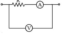
- 2In the circuit shown the resistance of voltmeter is $10,000\, ohm$ and that of ammeter is $20\,ohm$. The ammeter reading is $0.10\,Amp$ and voltmeter reading is $12$ $\mathrm{volt}.$ Then $R$ is equal to .............. $\Omega$View Solution
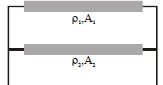
- 3Two conductors of same length are connected in parallel as shown in figure. Their cross-sectional areas $A_1$ and $A_2$ and their resistivities are ${\rho _1}$ and ${\rho _2}$ respectively. The equivalent resistivity of this combination isView Solution
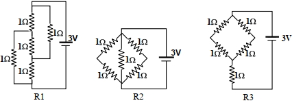
- 4Figure shows three resistor configurations $\mathrm{R} 1, \mathrm{R} 2$ and $\mathrm{R} 3$ connected to $3 \mathrm{~V}$ battery. If the power dissipated by the configuration $\mathrm{R} 1, \mathrm{R} 2$ and $\mathrm{R} 3$ is $\mathrm{P} 1, \mathrm{P} 2$ and $\mathrm{P} 3$, respectively, thenView Solution
Figure:
- 5View SolutionThe resistance of a conductor increases with
- 6An aluminium wire is stretched to make its length, $0.4 \,\%$ larger. Then percentage change in resistance is $.....\,\%$View Solution
- 7The resistance of a wire is $R$. If the length of the wire is doubled by stretching, then the new resistance will beView Solution
- 8An ideal gas mixture filled inside a balloon expands according to the relation $PV^{2/3} =$ constant. The temperature inside the balloon isView Solution
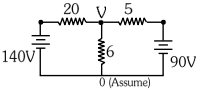
- 9The value of current in the $6 \,\Omega$ resistance is $....\,A$View Solution
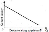
- 10An electric current flows along an insulated strip $PQ$ of a metallic conductor. The current density in the strip varies as shown in graph of figure. Which one of the following statements could explain this variation ?View Solution