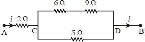
In the circuit shown in figure, the $5\,\Omega $ resistance develops $20.00\,cal/s$ due to the current flowing through it. The heat developed in $2\,\Omega $ resistance (in $cal/s$ ) is
AIIMS 2012, Medium
Download our app for free and get started
Let $\mathrm{I}_{1}$ be the current throug $5 \,\Omega$ resistance, $\mathrm{I}_{2}$ through $(6+9) \,\Omega$ resistance. Then as per question,
$\mathrm{I}_{1}^{2} \times 5=20$ or, $\mathrm{I}_{1}=2\, \mathrm{A}$
Potential difference across $C$ and $D=2 \times 5$ $=10 \,\mathrm{V}$
Current $I_{2}=\frac{10}{6+9}=\frac{2}{3}\, A$
Heat produced per second in $2\,\Omega$
$=\mathrm{I}^{2} \mathrm{R}\left(\frac{8}{3}\right)^{2} \times 2=14.2\,\mathrm{cal} / \mathrm{s}$

Download our appand get started for free
Experience the future of education. Simply download our apps or reach out to us for more information. Let's shape the future of learning together!No signup needed.*
Similar Questions
- 1In an experiment to find $emf$ of a cell using potentiometer, the length of null point for a cell of emf $1.5\,V$ is found to be $60\,cm$. If this cell is replaced by another cell of $emf\; E$. the length-of null point increases by $40\,cm$. The value of $E$ is $\frac{x}{10} V$. The value of $x$ is $............$View Solution
- 2Resistance of rod is calculated by measuring its length with help of meter scale of least count $1\ mm$ . Its radius is measured with help of screw gauge having $50$ division on circular scale and pitch is of $1\ mm$ . Resistivity of material is exact. Length of the wire is found to be $20\ cm$ and diameter of wire is $4\ mm$ . Find the percentage error in calculation of resistance ............... $\%$View Solution
- 3The energy dissipated by a resistor is $10 \,mJ$ in $1\,s$ when an electric current of $2\, mA$ flows through it. The resistance is $....... \Omega$View Solution
(Round off to the Nearest Integer)
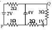
- 4In the circuit shown, what is the potential difference $V_{PQ}$? ................ $V$View Solution
- 5$4$ bulbs marked $40\, W$, $250\, V$ are connected in series with $250\, V$ mains. The total power is ............. $W$View Solution
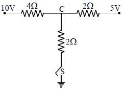
- 6As the switch $S$ is closed in the circuit shown in figure, current passed through it is .............View Solution
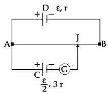
- 7A potentiometer wire $AB$ having length $L$ and resistance $12\, r$ is joined to a cell $D$ of $emf$ $\varepsilon $ and internal resistance $r$. A cell $C$ having $emf$ $\varepsilon /2$ and internal resistance $3r$ is connected. The length $AJ$ at which the galvanometer as shown in figure shows no deflection isView Solution
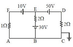
- 8The potential at point $E$ for the given figure is ................ $\mathrm{V}$View Solution
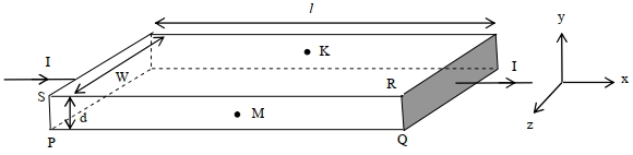
- 9In a thin rectangular metallic strip a constant current $I$ flows along the positive $x$-direction, as shown in the figure. The length, width and thickness of the strip are $\ell$, w and $d$, respectively. A uniform magnetic field $\vec{B}$ is applied on the strip along the positive $y$-direction. Due to this, the charge carriers experience a net deflection along the $z$ direction. This results in accumulation of charge carriers on the surface $P Q R S$ and appearance of equal and opposite charges on the face opposite to $PQRS$. A potential difference along the $z$-direction is thus developed. Charge accumulation continues until the magnetic force is balanced by the electric force. The current is assumed to be uniformly distributed on the cross section of the strip and carried by electrons.View Solution
$1.$ Consider two different metallic strips ($1$ and $2$) of the same material. Their lengths are the same, widths are $w_1$ and $w_2$ and thicknesses are $d_1$ and $d_2$, respectively. Two points $K$ and $M$ are symmetrically located on the opposite faces parallel to the $x$ - $y$ plane (see figure). $V _1$ and $V _2$ are the potential differences between $K$ and $M$ in strips $1$ and $2$ , respectively. Then, for a given current $I$ flowing through them in a given magnetic field strength $B$, the correct statement$(s)$ is(are)
$(A)$ If $w _1= w _2$ and $d _1=2 d _2$, then $V _2=2 V _1$
$(B)$ If $w_1=w_2$ and $d_1=2 d_2$, then $V_2=V_1$
$(C)$ If $w _1=2 w _2$ and $d _1= d _2$, then $V _2=2 V _1$
$(D)$ If $w _1=2 w _2$ and $d _1= d _2$, then $V _2= V _1$
$2.$ Consider two different metallic strips ($1$ and $2$) of same dimensions (lengths $\ell$, width w and thickness $d$ ) with carrier densities $n_1$ and $n_2$, respectively. Strip $1$ is placed in magnetic field $B_1$ and strip $2$ is placed in magnetic field $B_2$, both along positive $y$-directions. Then $V_1$ and $V_2$ are the potential differences developed between $K$ and $M$ in strips $1$ and $2$, respectively. Assuming that the current $I$ is the same for both the strips, the correct option$(s)$ is(are)
$(A)$ If $B_1=B_2$ and $n_1=2 n_2$, then $V_2=2 V_1$
$(B)$ If $B_1=B_2$ and $n_1=2 n_2$, then $V_2=V_1$
$(C)$ If $B _1=2 B _2$ and $n _1= n _2$, then $V _2=0.5 V _1$
$(D)$ If $B_1=2 B_2$ and $n_1=n_2$, then $V_2=V_1$
Give the answer question $1$ and $2.$
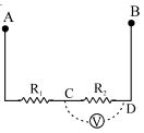
- 10Resistances $R_1$ and $R_2$ each $60\,\Omega$ are connected in series as shown in figure. The Potential difference between $A$ and $B$ is kept $120$ volt. Then what ............. $V$ will be the reading of voltmeter connected between the point $C$ and $D$ if resistance of voltmeter is $120\,\Omega .$View Solution