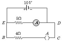
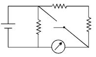
In the given figure, when key $A$ is opened, the reading of the ammeter $A$ will be ........... $A$
Easy
Download our app for free and get started
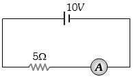
(b) The circuit will be as shown
$i = \frac{{10}}{5} = 2A$
$i = \frac{{10}}{5} = 2A$

Download our appand get started for free
Experience the future of education. Simply download our apps or reach out to us for more information. Let's shape the future of learning together!No signup needed.*
Similar Questions
- 1The total momentum of electrons in a straight wire of copper of length $1\, metre$ carrying a current of $16\, A$ isView Solution
- 2The resistance of a wire is$10\,\Omega $. Its length is increased by $10\%$ by stretching. The new resistance will now be .......... $\Omega$View Solution
- 3A battery of $e.m.f.$ $3\, volt$ and internal resistance $1.0\, ohm$ is connected in series with copper voltameter. The current flowing in the circuit is $1.5\, amperes$. The resistance of voltameter will be ........... $ohm$View Solution
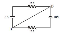
- 4Calculate the current in wire $BD$ ................ $A$View Solution
- 5In the circuit shown, the reading of the Ammeter is doubled after the switch is closed. Each resistor has a resistance $1\,\Omega $ and the ideal cell has an $e.m.f.$ $10\, V$. Then, the Ammeter has a coil resistance equal to ............... $\Omega$View Solution
- 6When a current of $2\,A$ flows in a battery from negative to positive terminal, the potential difference across it is $12\,V$. If a current of $3\,A$ flows in the opposite direction potential difference across the terminals of the battery is $15\,V$, the emf of the battery is ............... $\mathrm{V}$View Solution
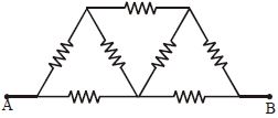
- 7In the network shown in the following figure, each resistance is $1\,ohm.$ The effective resistance between $A$ and $B$ isView Solution
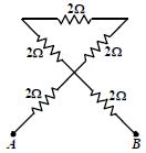
- 8For the circuit shown in the figure , the equivalent resistance between $A$ and $B$ is ............. $\Omega$View Solution
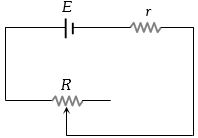
- 9A battery of $e.m.f.$ $E$ and internal resistance $r$ is connected to a variable resistor $R$ as shown here. Which one of the following is trueView Solution
- 10In the circuit shown, the potential difference between $A$ and $B$ is ............. $V$View Solution