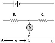
In the shown arrangement of the experiment of the meter bridge if $AC$ corresponding to null deflection of galvanometer is $x$, what would be its value if the radius of the wire $AB$ is doubled
IIT 2003, Medium
Download our app for free and get started
(a) Balancing length is independent of the cross sectional area of the wire.

Download our appand get started for free
Experience the future of education. Simply download our apps or reach out to us for more information. Let's shape the future of learning together!No signup needed.*
Similar Questions
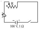
- 1The battery in the diagram is to be charged by the generator $G$. The generator has a terminal voltage of $120$ $\mathrm{volts}$ when the charging current is $10$ $\mathrm{amperes}.$ The battery has an $\mathrm{emf}$ of $100$ $\mathrm{volts}$ and an internal resistance of $1$ $\mathrm{ohm}.$ In order to charge the battery at $10$ $\mathrm{amperes}$ charging current, the resistance $R$ should be set at ................ $\Omega$View Solution
- 2Two wires have resistance of $2$ $\Omega$ and $4$ $\Omega$ connected to same voltage, ratio of heat dissipated at resistance isView Solution
- 3View SolutionSensitivity of potentiometer can be increased by
- 4A current $I$ flows through a uniform wire of diameter $d,$ when the mean drift velocity is $v_d.$ The same current will flow through a wire of diameter $d/2$ made of the same material, if the mean drift velocity of the electrons isView Solution
- 5A fuse wire with radius $1\, mm$ blows at $1.5\, amp$. The radius of the fuse wire of the same material to blow at $3\,A$ will beView Solution
- 6The terminal potential difference of a cell when short-circuited is ($E$ = $E.M.F.$ of the cell)View Solution
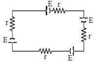
- 7Four identical cells of $EMF$ $E$ and internal resistance $r$ are connected as shown in figure, find terminal voltage across any one cellView Solution
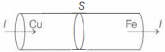
- 8Two rods of copper and iron with the same cross-sectional area are joined at $S$ and a steady current $I$ flows through the rods as shown in the figure. Choose the most appropriate representation of charges accumulated near the junction $S$.View Solution
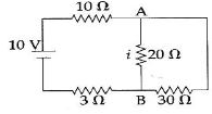
- 9In the electrical circuit shown in the figure, the current $i$ through the side $AB$ isView Solution
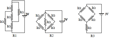
- 10Figure shows three resistor configurations $\mathrm{R} 1, \mathrm{R} 2$ and $\mathrm{R} 3$ connected to $3 \mathrm{~V}$ battery. If the power dissipated by the configuration $\mathrm{R} 1, \mathrm{R} 2$ and $\mathrm{R} 3$ is $\mathrm{P} 1, \mathrm{P} 2$ and $\mathrm{P} 3$, respectively, thenView Solution
Figure: