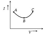
Suppose the drift velocity $v_d$ in a material varied with the applied electric field $E$ as ${v_d}\, \propto \,\sqrt E $ .Then $V - I$ graph for a wire made of such a material is best given by
JEE MAIN 2015, Diffcult
Download our app for free and get started
$i=n e A V_{d}$ and $V_{d} \propto \sqrt{E}$ (Given)
or, $i \propto \sqrt{E}$
$i^{2} \propto E$
$i^{2} \propto V$
Hence graph $(c)$ correctly dipicts the $V-I$ graph for a wire made of such type of material.

Download our appand get started for free
Experience the future of education. Simply download our apps or reach out to us for more information. Let's shape the future of learning together!No signup needed.*
Similar Questions
- 1A $5\;ampere$ fuse wire can withstand a maximum power of $1\; watt$ in the circuit. The resistance of the fuse wire isView Solution
- 2View SolutionAssertion : Ohm's law is applicable for all conducting elements.
Reason : Ohm's law is a fundamental law
- 3View SolutionResistance as shown in figure is negative at
- 4A uniform wire of resistance $R$ is uniformly compressed along its length, until its radius becomes $n$ times the original radius. Now resistance of the wire becomesView Solution
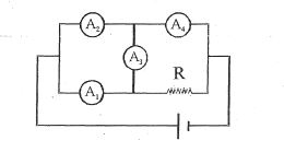
- 5Four ammeters with identical internal resistance $r$ and a resistor $R$ are connected to a current source as given. if reading of $A_1$ and $A_2$ is $3\ A$ and $5\ A$ respectively then the reading $A_4$ is ............. $A$View Solution
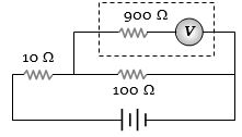
- 6The potential difference across the $100\,\Omega$ resistance in the following circuit is measured by a voltmeter of $900 \,\Omega$ resistance. The percentage error made in reading the potential difference isView Solution
- 7With a potentiometer null point were obtained at $140\, cm$ and $180\, cm$ with cells of $emf$ $1.1 \,V$ and one unknown $X\, volts$. Unknown $emf$ is .............. $V$View Solution
- 8Assume a hypothetical wire in which free electron density changes with temperature in proportionality $n\ \alpha \ T$ assuming $\tau $(Relaxation time of collision) and dimensions of wire remain unchanged with increasing temperature. Which one of the resistance $v/s$ temperature graph is trueView Solution
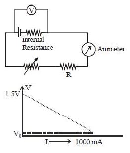
- 9To verify Ohm's law, a student connects the voltmeter across the battery as, shown in the figure. The measured voltage is plotted as a function of the current, and the following graph is obtained If $V_0$ is almost zero, identify the correct statementView Solution
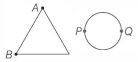
- 10A uniform metallic wire of length $L$ is mounted in two configurations. In configuration $1$ (triangle), it is an equilateral triangle and a voltage $V$ is applied to corners $A$ and $B$. In configuration $2$ (circle), it is bent in the form of a circle and the potential $V$ is applied at diametrically opposite points $P$ and $Q$. The ratio of the power dissipated in configuration $1$ to configuration $2$ isView Solution