A uniform wire of resistance $R$ is uniformly compressed along its length, until its radius becomes $n$ times the original radius. Now resistance of the wire becomes
Easy


Download our appand get started for free
Experience the future of education. Simply download our apps or reach out to us for more information. Let's shape the future of learning together!No signup needed.*
Similar Questions
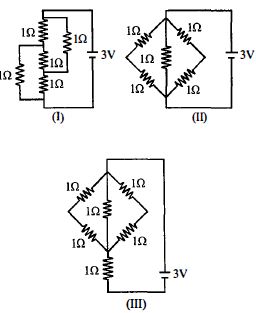
- 1The figure shows three circuits $I, II$ and $III$ which are connected to a $3\,V$ battery. If the powers dissipated by the configurations $I, II$ and $III$ are $P_1 , P_2$ and $P_3$ respectively, thenView Solution
- 2A $3\,^oC$ rise in temperature is observed in a conductor by passing a certain current. When the current is doubled, the rise in temperature will be ............. $^oC$View Solution
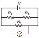
- 3In the circuit shown, $R_1$ is increased. What happens to the reading of the voltmeter (ideal)?View Solution
- 4View SolutionIn the circuit shown in figure, which of the statement is incorrect ?
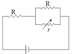
- 5In the circuit shown, the resistance $r$ is a variable resistance. If for $r = fR,$ the heat generation in $r$ is maximum then the value of $f$ isView Solution
- 6Give colors of the ring in sequence marked on a resistance of $56 \ k\Omega$ with tolerance $\pm 5\%$View Solution
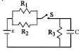
- 7The circuit shown in the figure consists of a battery of $emf$ $\varepsilon = 10 \,V$ ; a capacitor of capacitance $C = 1.0$ $ \mu F$ and three resistor of values $R_1 = 2$ $\Omega$ , $R_2 = 2$ $\Omega$ and $R_3 = 1$ $\Omega$ . Initially the capacitor is completely uncharged and the switch $S$ is open. The switch $S$ is closed at $t = 0.$View Solution
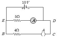
- 8In the given figure, when key $A$ is opened, the reading of the ammeter $A$ will be ........... $A$View Solution
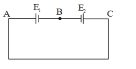
- 9Two cells are connected in opposition as shown. Cell $\mathrm{E}_1$ is of $8 \mathrm{~V}$ emf and $2 \ \Omega$ internal resistance; the cell $E_2$ is of $2 \mathrm{~V}$ emf and $4\ \Omega$ internal resistance. The terminal potential difference of cell $\mathrm{E}_2$ is:View Solution
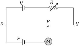
- 10A potentiometer circuit shown in the figure is set up to measure $e.m.f.$ of a cell $E$. As the point $P$ moves from $X$ to $Y$ the galvanometer $G$ shows deflection always in one direction, but the deflection decreases continuously until $Y$ is reached. In order to obtain balance point between $X$ and $Y$ it is necessary toView Solution