The current flowing through $R _2$ is:
JEE MAIN 2023, Medium


Download our appand get started for free
Experience the future of education. Simply download our apps or reach out to us for more information. Let's shape the future of learning together!No signup needed.*
Similar Questions
- 1For a cell of $e.m.f.$ $2\,V$, a balance is obtained for $50\, cm$ of the potentiometer wire. If the cell is shunted by a $2\,\Omega $ resistor and the balance is obtained across $40\, cm$ of the wire, then the internal resistance of the cell is ............. $\Omega $View Solution
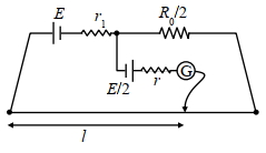
- 2In order to measure the internal resistance $r_1$ of a cell of emf $E$, a meter bridge of wire resistance $R_0=50 \Omega$, a resistance $R_0 / 2$, another cell of emf $E / 2$ (internal resistance $r$ ) and a galvanometer $G$ are used in a circuit, as shown in the figure. If the null point is found at $l=72 cm$, then the value of $r_1=$ . . . . $\Omega$View Solution
- 3The specific resistance of a wire is $\rho $, its volume is $3\,{m^3}$ and its resistance is $3\, ohms$, then its length will beView Solution
- 4$50\,\Omega $ and $100\,\Omega $ resistors are connected in series. This connection is connected with a battery of $2.4\, volts$. When a voltmeter of $100\,\Omega $ resistance is connected across $100\,\Omega $ resistor, then the reading of the voltmeter will be ............. $V$View Solution
- 5View SolutionThe relaxation time in conductors
- 6View SolutionElectric power is transmitted over long distances through conducting wires at high voltage because
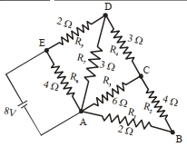
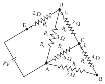
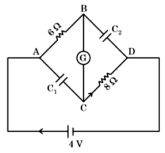
- 7In this figure the resistance of the coil of galvanometer $G$ is $2\,\Omega$. The emf of the cell is $4\,V$. The ratio of potential difference across $C_1$ and $C_2$ is:View Solution
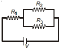
- 8Three identical resistors $R_1=R_2=R_3$ are connected as shown to a battery of constant e.m.f. The power dissipated is ...........View Solution
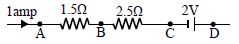
- 9In the circuit element given here, if the potential at point $B$, $V_B = 0$, then the potentials of $A$ and $D$ are given asView Solution
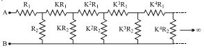
- 10The circuit diagram shown consists of a large number of element (each element has two resistors $R_1$ and $R_2$). The resistance of the resistors in each subsequent element differs by $a$ factor of $K = 1/2$ from the resistance of the resistors in the previous elements. The equivalent reistance between $A$ and $B$ shown in figure is :View Solution