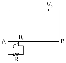
The sliding contact $C$ is at one fourth of the length of the potentiometer wire $( AB )$ from $A$ as shown in the circuit diagram. If the resistance of the wire $AB$ is $R _0$, then the potential drop $( V )$ across the resistor $R$ is
NEET 2022, Medium
Download our app for free and get started
In series, potential divides in direct ratio of resistance,
So, $V_{A C}=\frac{R_{A C}}{R_{A C}+R_{C B}} V_0$
$=\frac{\frac{ RR _0}{4 R + R _0}}{\frac{ RR _0}{4 R + R _0}+\frac{3 R _0}{4}} \times V _0=\frac{4 RV _0}{16 R +3 R _0}$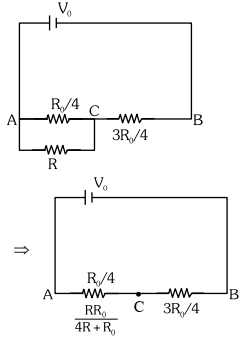

Download our appand get started for free
Experience the future of education. Simply download our apps or reach out to us for more information. Let's shape the future of learning together!No signup needed.*
Similar Questions
- 1A potentiometer wire of length $L$ and a resistance $r$ are connected in series with a battery of e.m.f. $E_0$ and a resistance $r_1$. An unknown e.m.f. $E$ is balanced at a length $l$ of the potentiometer wire. The e.m.f. $E$ will be given byView Solution
- 2The same mass of copper is drawn into two wires $1\, mm$ and $2\, mm$ thick. Two wires are connected in series and current is passed through them. Heat produced in the wire is in the ratioView Solution
- 3A resistor ${R_1}$ dissipates the power $P$ when connected to a certain generator. If the resistor ${R_2}$ is put in series with ${R_1}$, the power dissipated by ${R_1}$View Solution
- 4Two resistances $r_1$ and $r_2\left(r_1 < r_2\right)$ are joined in parallel. The equivalent resistance $R$ is such thatView Solution
- 5A potentiometer is used for the comparison of $e.m.f.$ of two cells ${E_1}$ and ${E_2}$. For cell ${E_1}$ the no deflection point is obtained at $20\,cm$ and for ${E_2}$ the no deflection point is obtained at $30\,cm$. The ratio of their $e.m.f.$'s will beView Solution
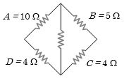
- 6In a typical Wheatstone network, the resistances in cyclic order are $A = 10 \,\Omega $, $B = 5 \,\Omega $, $C = 4 \,\Omega $ and $D = 4 \,\Omega $ for the bridge to be balancedView Solution
- 7In the figure shown, if the internal resistance of the battery is $1\, ohm$, the reading of the ammeter will be ............... $A$View Solution
- 8View SolutionAssertion : An electric bulb becomes dim, when the electric heater in parallel circuit is switched on.
Reason : Dimness decreases after sometime.
- 9To measure the internal resistance of a battery, potentiometer is used. For $\mathrm{R}=10 \Omega$, the balance point is observed at $\ell=500 \mathrm{~cm}$ and for $\mathrm{R}=1 \Omega$ the balance point is observed at $\ell=400 \mathrm{~cm}$. The internal resistance of the battery is approximately :View Solution
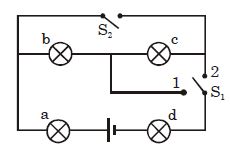
- 10Four lamps are connected in the way shown in the figure. When switch $S_2$ is open and switch $S_1$ is on position $-2$ , lamp $-b$ is the brightest, and lamp $-c$ and lamp $-d$ are the dimmest and are of the same brightness. Now $S_2$ is closed and $S_1$ is on position $-1$ , the sequence in brightness of the lamps is (with the first in the sequence being the brightest)View Solution