MCQ
Zener-diode is used in:
  • A
    Amplification
  • B
    Rectification
  • C
    Oscillator in producing oscillations
  • D
    Volatge regulation

Answer

  1. Volatge regulation

Explanation:

 A voltage regulator circuit can be designed using a zener diode to maintain a constant DC output voltage across the load in spite of variations in the input voltage or changes in the load current.

Need a full question paper?

Generate a complete, print-ready paper with questions like this in minutes — across 16+ boards, with answer keys.

Start Generating Free

Similar questions

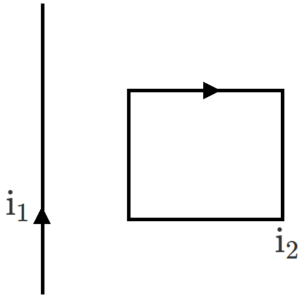
When the length and area of cross-section both are doubled, then its resistance

(a) Will become half

(b) Will be doubled

(c) Will remain the same

(d) Will become four times

In the given figure distance of the point from A where the electric field is zero is
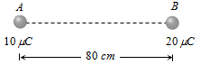
(a) 20 cm

(b) 10 cm

(c) 33 cm

(d) None of these

The angular speed of the electron in the nth orbit of Bohr hydrogen atom is?
A particle moves in a circular path with a continuously increasing speed. Its motion is:
  1. Periodic.
  2. Oscillatory.
  3. Simple harmonic.
  4. None of them.
If the two ends of a p-n junction are joined by a wire:
  1. There will not be a steady current in the circuit.
  2. There will be a steady current from the n-side to the p-side.
  3. There 'will a steady current from the p-side. to the n-side.
  4. There may or may not be a current depending upon the resistance of the connecting wire.
Huygens principle of secondary waves:
Consider the situation shown in figure. The straight wire is fixed but the loop can move under magnetic force. The loop will:

Suppose, the electron in a hydrogen atom makes transition from n = 3 to n = 2 in 10-8s. The order of the torque acting on the electron in this period, using the relation between torque and angular momentum as discussed in the chapter on rotational mechanics is:
Identify the direction in which a thin long piece of magnet comes to rest when suspended freely.
Figure (a) below shows a Wheatstone bridge in which P, Q, R, S are fixed resistances, G is a galvanometer and B is a battery. For this particular case the galvanometer shows zero deflection. Now, only the positions of B and G are interchanged,. as shown in figure (b). The new deflection of the galvanometer.