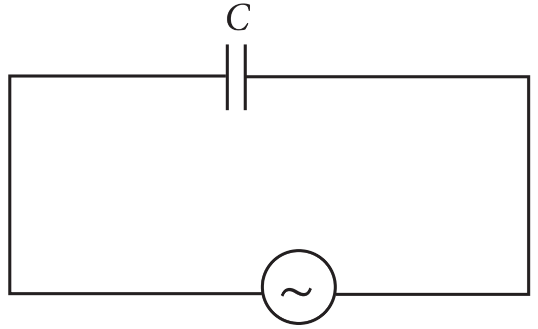
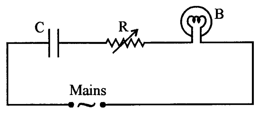
- Reactance of the capacitor will decrease, resulting in increase of the current in the circuit. Therefore the bulb will glow brighter.
- Increased resistance will decrease the current in the circuit, which will decrease glow of the bulb.
12 questions · timed · auto-graded

Explanation:
In an ideal transformer, there is no power loss. The efficiency of an ideal transformer is $\eta=1$ (i.e 100%) i.e. input power = output power.
Explanation:
Transformer is used to obtain desired ac voltage and current.
Explanation:
For a transformer, $\frac{\text{V}_\text{S}}{\text{V}_\text{p}}=\frac{\text{n}_\text{S}}{\text{n}_\text{p}}$
Where N denotes number of turns and V = voltage.
$\therefore{\text{V}_\text{S}}={\text{ac}\ 110}{\text{V}}$
Explanation:
In a transformer the primary and secondary currents are related by,
$\text{I}_\text{S}=\Big(\frac{\text{N}_\text{S}}{\text{N}_\text{P}}\Big)\text{I}_\text{P}$
And the Voltage are related by,
$\text{V}_\text{S}=\Big(\frac{\text{N}_\text{P}}{\text{N}_\text{S}}\Big)\text{V}_\text{P}$
where subscripts p and s refer to the primary and secondary of the transformer.
Here, $\text{V}_\text{P}=\text{V},\frac{\text{N}_\text{P}}{\text{N}_\text{S}}=4\ \therefore\text{I}_\text{P}=4\text{I}_\text{P}$
and, $\text{V}_\text{S}=\Big(\frac{1}{4}\Big)\text{V}=\frac{\text{V}}{4}$
Explanation:
The efficiency of the transformer is:
$\eta=\frac{\text{output power}(\text{p}_\text{out})}{\text{intput power}(\text{p}_\text{in})}\times100$
Here, Pout = 100W, Pin = (220V)(0.5A) = 110W
$\therefore\eta=\frac{100\text{W}}{110\text{W}}\times100=90\%$

Explanation:
Energy, $\text{E}=\frac{1}{2}\frac{\text{Q}^2}{\text{C}}=\frac{(10\times10^{-3})^2}{2\times50\times10^{-6}}=1\text{J}$
Explanation:
Frequency, $\upsilon=\frac{1}{2\pi\sqrt{\text{LC}}}$
$\upsilon=\frac{1}{2\pi\sqrt{20\times10^{-3}\times50\times10^{-6}}}$
$=\frac{10^3}{2\pi}=159.24\text{Hz}$
Explanation:
Total time period, $\text{T}=\frac{1}{\upsilon}=\frac{1}{159.24}=6.20\text{ms}$
Total charge on capacitor at time t, $\text{Q}'=\text{Q}\cos\frac{2\pi}{\text{T}}\text{t}$
For energy stored is electrical, we can write Q' = ± Q.
Hence, energy stored in the capacitor is completely electrical at, $\text{t}=0,\frac{\text{T}}{2},\text{t},\frac{3\text{T}}{2},\ ......$
Explanation:
Magnetic energy is maximum when electrical energy is equal to zero.
Hence, $\text{t}=\frac{\text{T}}{4},\frac{\text{3T}}{4},\frac{\text{5T}}{4},\ ....$
Explanation:
$\text{X}_\text{L}=\omega_\text{L}=2\pi\upsilon\text{L}$
$2 × 3.14 × 159.24 × 20 × 10^{-3}$
$\Rightarrow\text{X}_\text{L}=20\Omega$

Explanation:
Inductive reactance,
$\text{X}_\text{L}= \text{W}_\text{L}=2\pi\mu\text{L}$
$=2\pi\times100\times14\times10^{-3}$
$\text{X}_\text{L}=8.8\Omega$
Explanation:
In an inductor vol tag: leads the current by $\frac{\pi}{2}$ or current lags the voltage by $\frac{\pi}{2}.$
Explanation:
The current in the inductor coil is given by,
$\text{I}_0=\frac{\text{E}_0}{\text{X}_\text{L}}=\frac{\sqrt{2}\text{E}_\text{V}}{2\pi\mu\text{L}}$
$\text{L}=\frac{\sqrt{2}\text{E}_\text{V}}{2\pi\mu\text{I}_0}=\frac{1.414\times200}{2\times3.14\times50\times0.9}=1\text{H}$
Explanation:
Inductive reactance,
$\text{X}_\text{L}= \text{W}_\text{L}=2\pi\mu\text{L}$
$=2\pi\times3.14\times50\times2=628\Omega$
$\text{I}_0=\frac{\text{E}_0}{\text{X}_\text{L}}$
$\Rightarrow\text{I}_0=\frac{\sqrt{2}\times\text{E}_\text{V}}{\text{X}_\text{L}}=\frac{\sqrt{2}\times150}{628}=0.337\text{A}$
$\Rightarrow\ \text{E}_0=\text{E}_\text{rms}\sqrt{2}$
$=\sqrt{2}\times220=1.414\times220$
$=311.08\text{V}=311\text{V}$
$\text{I}=\frac{\text{I}_0}{\sqrt{2}}$
$\Rightarrow\ \frac{\text{I}_0}{\sqrt{2}}=\text{I}_0\sin\omega\text{t}$
$\Rightarrow\ \omega\text{t}=\frac{\pi}{4}$
$\Rightarrow\ \text{t}=\frac{\pi}{4\omega}=\frac{\pi}{4\times22\pi\text{f}}$
$=\frac{\pi}{8\pi50}=\frac{1}{400}=2.5\text{ms}$

Explanation:
Resistance of the two wire lines carrying power $=0.5\frac{\Omega}{\text{Km}}$
Total resistance $=(15+15)0.5=15\Omega$
Explanation:
Line power loss = I2R
RMS current in the coil,
$\text{I}=\frac{\text{P}}{\text{V}_1}=\frac{800\times10^3}{4000}=200\text{A}$
$\therefore$ Power loss = (200)2 × 15 = 600kW
Explanation:
Assuming that the power loss is negligible due to the leakage of the current.
The total power supplied by the plant,
= 800kW + 600kW = 1400kW
Explanation:
Voltage drop in the power line = IR
= 200 × 15 = 3000V
Explanation:
Total voltage transmitted from the plant,
= 3000V + 4000V = 7000V

Explanation:
Inductance, L = 80mH = 80 × 10-3H
Capacitance, $\text{C}=60\mu\text{F}=60\times10^{-6}\text{F},\ \text{V}=230\text{V}$
Frequency, $\upsilon=50\text{Hz}$
$\omega=2\pi\upsilon=100\pi\ \text{red}\ \text{s}^{-1}$
Peak voltage, $\text{V}_0=\text{V}\sqrt{2}=230\sqrt{2}\text{V}$
Maximum current is given by, $\text{I}_0=\frac{\text{V}_0}{\Big(\omega\text{L}-\frac{1}{\omega\text{C}}\Big)}$
$\text{I}_0=\frac{230\sqrt{2}}{\Big(100\pi\times80\times10^{-3}-\frac{1}{100\pi\times60\times10^{-6}}\Big)}$
$\text{I}_0=\frac{230\sqrt{2}}{\Big(8\pi-\frac{1000}{6\pi}\Big)}=-11.63\text{A}$
Amplitude of maximum current, I0 = 11.63A
Explanation:
rms value of current,
$\text{I}=\frac{\text{I}_0}{\sqrt{2}}=-\frac{-11.63}{\sqrt{2}}=-8.23\text{A}$
Negative sign appears as $\text{W}_\text{L}<\frac{1}{\text{W}_\text{C}}.$
Explanation:
Average power consumed by the inductor is zero because of phase difference of $\frac{\pi}{2}$ between voltage and current through inductor.
Explanation:
Average power consumed by the capacitor is zero because of phase difference of $\frac{\pi}{2}$ between voltage and current through capacitor.

Explanation:
Average power transferred per cycle to resistance is $\text{P}_\text{V} = \text{I}^2_\text{V}\text{R}$
As, $\text{X}_\text{L}=\omega_\text{L}=2\pi\upsilon\text{L}=2\times\frac{22}{7}\times60\times0.6=226.28\Omega$
$\text{X}_\text{C}=\frac{1}{\omega\text{C}}=\frac{1}{2\pi\upsilon\text{C}}$
$=\frac{1}{2\times\frac{22}{7}\times60\times50\times10^{-6}}=53.03\Omega$
$\text{Z}=\sqrt{\text{R}^2+(\text{X}_\text{L}-\text{X}_\text{C})^2}$
$=\sqrt{\text{10}^2+(\text{226.28}_-\text{53.03})^2}=173.53\Omega$
$\text{I}_\text{V}=\frac{\text{E}_\text{V}}{\text{R}}=\frac{230}{173.53}=1.32\text{A}$
$\text{P}_\text{V} = \text{I}^2_\text{V}\text{R}=(1.32)^2\times10=17.42\text{W}$
Explanation:
$\text{P}_\text{V}=\text{E}_\text{V}\text{I}_\text{V}\cos\phi.$
In a capacitor, phase difference, $\phi=90^\circ$
$\therefore\text{P}_\text{L}=\text{E}_\text{V}\text{I}_\text{V}\cos90^\circ=\text{Zero}$
Explanation:
$\text{P}_\text{L}=\text{E}_\text{V}\text{I}_\text{V}\cos\phi.$
In an inductor, phase difference, $\phi=90^\circ$
$\therefore\text{P}_\text{L}=\text{E}_\text{V}\text{I}_\text{V}\cos90^\circ=\text{Zero}$
Explanation:
Total power absorbed per cycle
P = PR + PC + PL = 17.42 + 0 + 0 = 17.42W
Explanation:
Energy spent = power × time
= 17.42 × 60 × 60
= 6.2 × 10⁴ Joule

Solution:
Ohm is the unit of capacitive reactance.
Solution:
Capacitive reactance, $\text{X}_\text{C}=\frac{1}{\omega\text{C}}=\frac{1}{2\pi\mu\text{C}}$
$=\frac{1}{2\pi\times10^6\times5\times10^{-6}}$
$=0.032\Omega$
Solution:
In capacitive circuit, resistance to the flow of current is offered by the capacitor.
Solution:
Current, $\text{l}_\text{v}=\frac{\text{E}_\text{V}}{\text{X}_\text{C}}=\frac{1}{\frac{1}{2\pi\mu\text{C}}}=(2\pi\mu\text{C})\text{E}_\text{V}$
$\text{I}_\text{v}=2\times3.14\times50\times10^{-6}\times200$
$=6.28 × 10^{-2}\text{A}$

Explanation:
Here, L = 0.12H, e = 480nF = 480 × 10-9F
$\text{R} = 23\Omega,$ V = 230V
$\text{V}_0=\sqrt{2}\times230=325.22\text{V}$
$\text{I}_0=\frac{\text{V}_0}{\sqrt{\text{R}^2+\Big(\omega\text{L}-\frac{1}{\omega\text{C}}\Big)^2}}$
At resonance, $\omega\text{L}-\frac{1}{\omega\text{C}}=0$
$\omega=\frac{1}{\sqrt{\text{LC}}}=\frac{1}{\sqrt{0.12\times480\times10^9}}=4166.67\ \text{rad}\ \text{s}^{-1}$
$\upsilon_\text{R}=\frac{4166.67}{2\times3.14}=663.48\text{H}_\text{z}$
Explanation:
Current, $\text{I}_0=\frac{\text{V}_0}{\text{R}}=\frac{325.22}{23}=14.14\text{A}$
Explanation:
Maximum power, $\text{P}_\text{max}=\frac{1}{2}(\text{I}_0)^2\text{R}$
$=\frac{1}{2}\times(14.14)^2\times23=2299.3\text{W}$
Explanation:
Quality factor, $\text{Q}=\frac{\text{X}_\text{R}}{\text{R}}=\frac{\omega_\text{r}\text{L}}{\text{R}}$
$=\frac{4166.67\times0.12}{23}=21.74$
Explanation:
As, $\frac{\text{E}_\text{s}}{\text{E}_\text{p}}=\frac{\text{n}_\text{s}}{\text{n}_\text{p}}$
$\Rightarrow\text{E}_\text{s}=\text{E}_\text{p}\times\frac{\text{n}_\text{p}}{\text{n}_\text{p}}$
$=\frac{120\times50}{2000}=3\text{V}$
Explanation:
$\text{I}_0=\frac{\text{E}_\text{S}}{\text{R}}\Rightarrow\text{I}_0=\frac{3}{0.6}=5\text{A}$
Explanation:
As, $\frac{\text{I}_\text{P}}{\text{I}_\text{S}}=\frac{\text{E}_\text{S}}{\text{E}_\text{P}}$
$\Rightarrow\text{I}_\text{p}=\frac{\text{E}_\text{S}}{\text{E}_\text{P}}\times\text{I}_\text{S}=\frac{3}{120}\times5=0.125\text{A}$
Explanation:
Power in primary, PP = EP × IP = 120 × 0.125
= 15W
Explanation:
Power in secondary coil, PS = ES × IS = 3 × 5
= 15W

Explanation:
Given, $\text{R}=12\Omega,\ \text{X}_C=14\Omega,\ \text{L}=0.1\text{H}$
$\text{X}_L=\omega_\text{L}=2\pi\upsilon\text{L}$
$= 2\times3.14\times50\times0.1$
$=31.4\Omega$
Explanation:
Impedance, $\text{Z}=\sqrt{\text{R}^2+(\text{X}_\text{L}-\text{X}_\text{C})^2}$
$=\sqrt{\text{12}^2+(\text{31.4}-\text{14})^2}$
$=21.13\Omega$
Explanation:
$\text{l}_\text{v}=\frac{\text{E}_\text{v}}{\text{Z}}=\frac{200\text{V}}{21.13}$
$= 9.46\text{A}$
Explanation:
$\tan\phi=\frac{\text{X}_\text{L}-\text{X}_\text{C}}{\text{R}}$
$=\frac{3.14-14}{12}=1.45$
$\phi\tan^{-1}(1.45)=55^\circ4'$