Question 14 Marks
What are eddy currents? State applications of eddy currents.
AnswerWhenever a conductor or a part of it is moved in a magnetic field “cutting” magnetic field lines, or placed in a changing magnetic field, the free electrons in the bulk of the metal start circulating in closed paths equivalent to current-carrying loops. These loop currents resemble eddies in a fluid stream and are hence called eddy or Foucault currents [after Jean Bernard Leon Foucault (1819-68), French physicist, who first detected them].
Applications :
(1) Dead-beat galvanometer : A pivoted moving-coil galvanometer used for measuring current has the coil wound on a light aluminium frame. The rotation of the metal frame in magnetic field produces eddy currents in the frame which opposes the rotation and the coil is brought to rest quickly. This makes the galvanometer dead-beat.
(2) Electric brakes : When a conducting plate is pushed into a magnetic field, or pulled out, very quickly, the interaction between the eddy currents in the moving conductor and the field retards the motion. This property of eddy currents is used as a method of braking in vehicles.
View full question & answer→Question 24 Marks
State and explain Lenz’s law in the light of principle of conservation of energy.
AnswerLenz’s law : The direction of the induced current is such as to oppose the change that produces it.
The change that induces a current may be (i) the motion of a conductor in a magnetic field or (ii) the change of the magnetic flux through a stationary circuit.
Explanation : Consider Faraday’s magnet-and- coil experiment. If the bar magnet is moved towards the coil with its N-pole facing the coil, as in Fig., the number of magnetic lines of induction (pointing to the left) through the coil increases. The induced current in the coil sets up a magnetic field of its own pointing to the right (as given by Amperes right-hand rule) to oppose the growing flux due to the magnet. Hence, to move the magnet towards the coil against this repulsive flux of the induced current, we must do work. The work done shows up as electric energy in the coil.
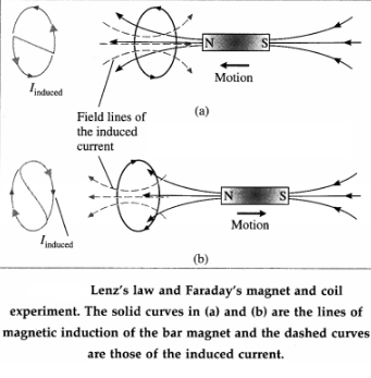
When the magnet is withdrawn, with its N-pole still facing the coil, the number of magnetic lines of induction (pointing left) through the coil decreases. The induced current reverses its direction to supplement the decreasing flux with its own, as shown in Fig.. Facing the coil along the magnet, the induced current is in the clockwise sense. The electric energy in the coil comes from the work done to withdraw the magnet, now against an attractive force. Thus, we see that Lenz’s law is a consequence of the law of conservation of energy.
[Note : The above law was discovered by Heinrich Friedrich Emil Lenz (1804-65), Russian physicist.]
View full question & answer→Question 34 Marks
In a Faraday disc dynamo, a metal disc of radius R rotates with an angular velocity ω about an axis perpendicular to the plane of the disc and passing through its centre. The disc is placed in a magnetic field B acting perpendicular to the plane of the disc. Determine the induced emf between the rim and the axis of the disc.
AnswerSuppose a thin conducting disc of radius $R$ is rotated anticlockwise, about its axis, in a plane perpendicular to a uniform magnetic field of induction $\vec{B}$ (see the figure in the above Note for reference). $\vec{B}$ points downwards. Let the constant angular speed of the disc be $\omega$.Consider an infinitesimal element of radial thickness dr at a distance $r$ from the rotation axis. In one rotation, the area traced by the element is $dA =2 \pi rdr$. Therefore, the time rate at which the element traces out the area is $\frac{d A}{d t}=$ frequency of rotation $x dA = fdA$ where $f=\frac{\omega}{2 \pi}$ is the frequency of rotation.
$
\therefore \frac{d A}{d t}=\frac{\omega}{2 \pi}(2 \pi r d r)=\omega r d r
$
The total emf induced between the axle and the rim of the rotating disc is
$
|e|=\int B \frac{d A}{d t}=\int_0^R B \omega r d r=B \omega \int_0^R r d r=B \omega \frac{R^2}{2}
$
For anticlockwise rotation in $\vec{B}$ pointing down, the axle is at a higher potential.
View full question & answer→Question 44 Marks
Calculate the value of induced emf between the ends of an axle of a railway carriage $1.75\ m$ long traveling on level ground with a uniform velocity of $50\ km$ per hour. The vertical component of Earth's magnetic field $\left(B_v\right)$ is given to be $5 \times 10^{-5} T$.
AnswerData: $I =1.75 m , v =50 km / h =50 \times \frac{5}{18} m / s$
$B _{ v }=5 \times 10^{-5} T$
The area swept out by the wing per unit time $=1 v$.
$\therefore$ The magnetic flux cut by the wing per unit time
$ =\frac{d \Phi_{ m }}{d t}= B _{ v }( lv )$
$=\left(5 \times 10^{-5}\right)(1.75)\left(50 \times \frac{5}{18}\right)=121.5 \times 10^{-5}$
$=1.215 mWb / s $
Therefore, the magnitude of the induced emf,
$|e|=1.215\ mV$
[Note: In the northern hemisphere, the vertical com ponent of the Earth's magnetic induction is downwards. Using Fleming's right hand rule, the port (left) wing-tip would be positive.]
View full question & answer→Question 54 Marks
The flux rule is the terminology that Feynman used to refer to the law relating magnetic flux to emf. (RP Feynman, Feynman lectures on Physics, Vol II)
AnswerModern applications of Faraday’s law of induction :
- Electric generators and motors
- Dynamos in vehicles
- Transformers
- Induction furnaces (industrial), induction cooking stoves (domestic)
- Radio communication
- Magnetic flow meters and energy meters
- Metal detectors at security checks .
- Magnetic hard disk and tape, storage and retrieval
- Graphics tablets
- ATM Credit/debit cards, ATM and point-of-sale (POS) machines
- Pacemakers
Faraday’s second law of electromagnetic induction is referred by some as the “flux rule”.
View full question & answer→Question 64 Marks
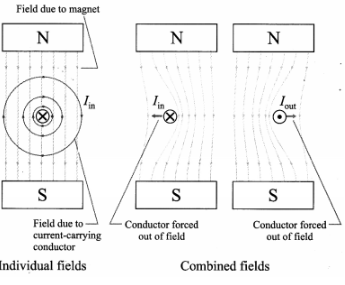
If a wire without any current is kept in a magnetic field, then it experiences no force as shown in figure (a). But when the wire is carrying a current into the plane of the paper in the magnetic field, a force will be exerted on the wire towards the left as shown in the figure (b). The field will be strengthened on the right side of the wire where the lines of force are in the same direction as that of the magnetic field and weakened on the left side where the field lines are in opposite direction to that of the applied magnetic field. For a wire carrying a current out of the plane of the paper, the force will act to the right as shown in figure (c).
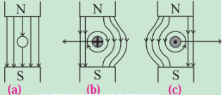
AnswerForce on a current-carrying conductor in a magnetic field, $\vec{F}=I \vec{L} \times \vec{B}$ (Refer unit 10.5). The field due to acurrent-carrying straight conductor is given by right- hand grip rule. As shown in the figure below, the combined field due to a permanent magnet and a current-carrying conductor force the conductor out of the field. The field is strengthened where the two fields are in the same direction and add constructively while the field is weakened where the two fields are opposite in direction.
View full question & answer→Question 74 Marks
The primary of a transformer has $40$ turns and works on $100 V$ and $100 W$. Find the number of turns in the secondary to step up the voltage to $400 V$. Also calculate the current in the secondary and primary.
AnswerData : $N_p=40, V_p=100 V , $
$P_p=100 W , V_S=400 V$
$(i)\ \frac{V_{ S }}{V_{ P }}=\frac{N_{ S }}{N_{ P }}$
$\therefore N_{ S }=N_{ P } \frac{V_{ S }}{V_{ P }}$
$\therefore N_{ S }=40 \times \frac{400}{100}=160$
This gives the number of turns in the secondary coil.
$(ii)$ Assuming $P_S=P_S=100 W_r$
$V _{ S } I _{ S }=100 W$
$\therefore I_S=\frac{100}{V_{ s }}=\frac{100}{400}=0.25 A$
This gives the current in the secondary coil.
$(iii)\ V_p \cdot I_p=P_p $
$\therefore I_p=\frac{P_p}{V_{ p }}=\frac{100}{100}=1 A$
This gives the current in the primary coil.
View full question & answer→MCQ 84 Marks
Two coils of $100$ turns and $200$ turns have self inductances $25\ mH$ and $40\ mH$, respectively. Their mutual inductance is $3\ mH$. If a $6\ mA$ current in the first coil is changing at the rate of $4\ A / s$, calculate
AnswerData: $ N _1=100, N _2=200, $
$L _1=25\ mH , L _2=40\ mH ,$
$l _1=6\ mA _1 dl _1 / dt =4 A / s$
$(a)$ The flux per unit turn in coil $1 ,$
$\Phi_{21}=\frac{L_1 I_1}{N_1}$
$=\frac{\left(25 \times 10^{-3}\right)\left(6 \times 10^{-3}\right)}{100}$
$=1.5 \times 10^{-6} Wb $
$=1.5 \mu Wb$
$(b)$ The magnitude of the self induced emf in coil $1$ is
$L_1=\frac{d I_1}{d t}=\left(25 \times 10^{-3}\right)(4)=0.1 V$
$(c)$ The flux per unit turn in coil $2 ,$
$\Phi_{21}=\frac{M I_1}{N_2}$
$=\frac{\left(3 \times 10^{-3}\right)\left(6 \times 10^{-3}\right)}{200}$
$=90 \times 10^{-9} Wb $
$=90 nWb$
$(d)$ The mutually induced emf in coil $2$ is
$e_{21}=M \frac{d I_1}{d t}=\left(3 \times 10^{-3}\right)(4)$
$=12 \times 10^{-3} V$
$=12 mV$
View full question & answer→Question 94 Marks
When a current changes from $4 A$ to $12 A$ in $0.5 s$ in the primary coil, an induced emf of 50 $mV$ is generated in the secondary coil. What is the mutual inductance between the two coils ? What will be the emf induced in the secondary, if the current in the primary changes from 3 A to $9 A$ in $0.02 s$ ?
Answer$
\begin{array}{c}
\text { Data : } I_{i 1}=4 A , I_{ f 1}=12 A , \Delta t _1=0.5 s _{ r } \Delta t _2=0.02 s \\
I_{ i 2}=3 A , I_{ f 2}=9 A , e_{ S 1}=5 \times 10^{-2} V \\
e_{ S }=-M \frac{d I_{ P }}{d t}
\end{array}
$
In the first case, $\frac{\Delta I_{ P }}{\Delta t}=\frac{I_{ f 1}-I_{ i 1}}{\Delta t_1}=\frac{12-4}{0.5}=16 A / s$
$\therefore$ The mutual inductance between the coils,
$
\begin{aligned}
M & =\frac{\left|e_{S_1}\right|}{\Delta I_{ p } / \Delta t}=\frac{5 \times 10^{-2}}{16} \\
& =3.125 \times 10^{-3} H =3.125 mH
\end{aligned}
$
In the second case, $\frac{\Delta I_{ P }}{\Delta t}=\frac{I_{ I _2}-I_{ i 2}}{\Delta t_2}=\frac{9-3}{0.02}=300 A / s$
$\therefore$ The emf induced in the secondary,
$
e_{\$ 1}=-\left(3.125 \times 10^{-3}\right)(300)=-0.9375 V
$
View full question & answer→Question 104 Marks
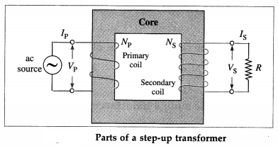
Derive the relation $\frac{V_{ S }}{V_{ p }}=\frac{N_{ S }}{N_{ p }}$ for a transformer. Hence, explain a step-up and a step-down trans-former. Also, show that $\frac{I_p}{I_{ S }}=\frac{N_{ S }}{N_{ p }}$###Derive expressions for the emf and current for a transformer in terms of the turns ratio.
AnswerAn alternating emf VP from an ac source is applied across the primary coil of a transformer, shown in figure.
This sets up an alternating current fP in the primary circuit and also produces an alternating magnetic flux through the primary coil such that
$
V_p=-N_p \frac{d \Phi_p}{d t}
$
where $N_p$ is the number of turns of the primary coil and $\Phi_p$ is the magnetic flux through each turn.
Assuming an ideal transformer (i.e., there is no leakage of magnetic flux), the same magnetic flux links both the primary and the secondary coils, i.e., $\Phi_p=\Phi_S$.
As a result, the alternating emf induced in the secondary coil,
$
V_S=-N_S \frac{d \Phi s}{d t}=-N_S \frac{d \Phi_p}{d t}
$
where $N_s$ is the number of turns of the secondary coil.
From Eqs. (1) and (2),
$
\frac{V_{ S }}{V_{ p }}=\frac{N_{ S }}{N_{ p }} \text { or } V_{ S }=V_p \frac{N_{ S }}{N_{ p }}
$
Case (1) i If $N_S>N_p, V_S>V_p$. Then, the trans-former is called a step-up transformer.
Case (2) : If $N_S<N_p, V_S<V_p$. Then the transformer is called a step-down transformer.
Ignoring power losses, the power delivered to the primary coil equals that taken out of the secondary coil, so that $V_p l_p=V_S I_s$
From Eqs. (3) and (4),
$
\frac{I_{ p }}{I_{ S }}=\frac{V_{ S }}{V_{ p }}=\frac{N_{ S }}{N_{ p }}
$
View full question & answer→Question 114 Marks
Derive the relationship $\frac{V_{ P }}{V_{ S }}=\frac{I_{ S }}{I_{ P }}$ for a transformer.
AnswerAn alternating emf VP from an ac source is applied across the primary coil of a transformer. This sets up an alternating current IP in the primary circuit and also produces an alternating magnetic flux through the primary coil such that $V _{ P }=- N _{ P } \frac{d \Phi_{ P }}{d t}$,
where $N_p$ is the number of turns of the primary coil and $\Phi_p$ is the magnetic flux through each turn.
Assuming an ideal transformer (i.e., there is no leakage of magnetic flux), the same magnetic flux links both the primary and the secondary coils,
$
\text { i. e., } \Phi_p=\Phi_5
$
As a result, the alternating emf induced in the secondary coil,
$
V _S== N _S \frac{d \Phi_{ S }}{d t}=- N _S \frac{d \Phi_{ p }}{d t}
$
where $N_S$ is the number of turns of the secondary coil. If the secondary circuit is completed by a resistance $R$, the secondary current is $I_S=V_S / R$, assuming the resistance of the coil to be far less than R. Ignoring power losses, the power delivered to the primary coil equals that taken out of the secondary coil, so $V _{ p } I _{ p }= V _{ S } I _{ s }$.
$
\therefore \frac{V_{ p }}{V_{ S }}=\frac{I_{ S }}{I_{ p }}
$
which is the required expression. View full question & answer→Question 124 Marks
Describe the construction and working of a transformer with a neat labelled diagram.
AnswerConstruction : A transformer consists of two coils, primary and secondary, wound on two arms of a rectangular frame called the core.
(1) Primary coil : It consists of an insulated copper wire wound on one arm of the core. Input voltage is applied at the ends of this coil.
In a step-up transformer, thick copper wire is used for primary coil. In a step-down transformer, thin copper wire is used for primary coil.
(2) Secondary coil : It consists of an insulated copper wire wound on the other arm of the core. The output voltage is obtained at the ends of this coil.
In a step-up transformer, thin copper wire is used for secondary coil. In a step-down transformer, thick copper wire is used for secondary coil.
(3) Core : It consists of thin rectangular frames of soft iron stacked together, but insulated from each other. A core prepared by stacking thin sheets rather than using a single thick sheet helps reduce eddy currents.
Working : When the terminals of the primary coil are connected to a source of an alternating emf (input voltage), there is an alternating current through it. The alternating current produces a time varying magnetic field in the core of the transformer. The magnetic flux associated with the secondary coil thus varies periodically with time according to the current in the primary coil. Therefore, an alternating emf (output voltage) is induced in the secondary coil.
View full question & answer→Question 134 Marks
Show that the mutual inductance for a pair of inductively coupled coils/circuits of self inductances $L_1$ and $L_2$ is given by $M=K \sqrt{L_1 L_2}$, where $K$ is the coupling coefficient.
AnswerConsider a pair of inductively coupled coils having $N_1$ and $N_2$ turns, shown in figure
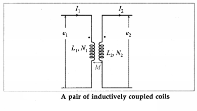
A current $I_1(t)$ sets up a flux $N_1 \Phi_1(t)$ in coil $1$ and induces a current $I_2(t)$ and flux $N_2 \Phi_2(t)$ in coil $2$. Then, the self inductances of the coils are
$L_1=\frac{N_1 \Phi_1}{I_1} \text { and } L_2=\frac{N_2 \Phi_2}{l_2}$
and their mutual inductance is
$M=\frac{N_2 \Phi_{21}}{I_1}=\frac{N_1 \Phi_{12}}{I_2}$
where $N_1 \Phi_{12}$ and $N_2 \Phi_{21}$ are the flux linkages of coils $1$ and $2$, respectively. If $K$ is the coupling coefficient,
$\Phi_{21}=K \Phi_1 \text { and } \Phi_{12}=K \Phi_2$
$\therefore M=\frac{N_2\left(K \Phi_1\right)}{I_1}=\frac{N_1\left(K \Phi_2\right)}{I_2}$
$\therefore M=K L_1=K L_2$
$\therefore M^2=K^2 L_1 L_2$
$\therefore M=K \sqrt{L_1 L_2}$
as required.
Alternate method:
Consider a pair of inductively coupled coils shown in above figure.We assume that $l_1(t), l_2(t)$ are zero at $t=0$, as also the magnetic energy of the system.
The induced emfs are
$e_1=L_1 \frac{d I_1}{d t}+M \frac{d I_2}{d t} \text { and } e_2=L_2 \frac{d I_2}{d t}+M \frac{d I_1}{d t} \ldots$
The net energy Input to the system shown in figure at time $t$ is given by
$W(t)=\int_0^t\left[e_1 I_1+e_2 I_2\right] d t$
$=\int_0^t\left[L_1 I_1 \frac{d I_1}{d t}+M I_1 \frac{d I_2}{d t}+L_2 I_2 \frac{d I_2}{d t}+M I_2 \frac{d I_1}{d t}\right] d t$
$=\frac{1}{2} L_1\left(I_1\right)^2+\frac{1}{2} L_2\left(I_2\right)^2+M I_1 I_2$
If one current enters a dot marked terminal while the other leaves a dot marked terminal, Eq.
$(2)$ becomes
$W(t)=\frac{1}{2} L_1\left(l_1\right)^2+\frac{1}{2} L_2\left(l_1\right)^2-M I_1 I_2$
The net electrical energy input to the system is non-negative, $W(t) \geq 0$. We rearrange Eq.$(3)$ as
$W(t)=\frac{1}{2}\left(\sqrt{L_1} I_1-\frac{M}{\sqrt{L_1}} I_2\right)^2+\left(L_2-\frac{M^2}{L_1}\right) I_2^2$
The first term in the parenthesis on the right hand side of Eq. $(4)$ is positive for all values of $I _1$ and $I _2$ Thus, for the second term also to be non-negative,
$L_2-\frac{M^2}{L_1} \geqslant 0$
$\text { or } \frac{L_1 L_2-M^2}{L_1} \geqslant 0$
or $\frac{L_1 L_2-M^2}{L_1} \geqslant 0$
or $L_1 L_2-M^2 \geqslant 0$ or $M \leqslant \sqrt{L_1 L_2}$
$\therefore M=K \sqrt{L_1 L_2}$
where the coupling coefficient $K$ is a non$-$negtive number, $0 \leq K \leq 1$, and is independent of the reference directions of the currents in the coils. View full question & answer→Question 144 Marks
A solenoid of $N_1$ turns has length $l_1$ and radius $R_1$, and a second smaller solenoid of $N_2$ turns has length $I _2$ and radius $R_2$. The smaller solenoid is placed coaxially and completely inside the larger solenoid. What is their mutual inductance?
AnswerAssuming the larger solenoid to be ideal, the magnetic field within it may be considered uniform, so the flux through the small solenoid due to the larger solenoid is also uniform.
Assuming a current $l _1$ in the larger solenoid, the magnitude of the magnetic field at points within the small solenoid due to the larger one is
$
B _1=\mu_0 \frac{N_1}{l_1} l _1
$
Then, the flux $\Phi_{21}$ through each turn of the small coil is $\Phi_{21}=B_1 A_2$
where is $A_2=\pi R^2{2}_,$, the area enclosed by the turn. Thus, the flux linkage in the small solenoid with its $N _2$ turns is
$
N _2 \Phi_{21}= N _2 B _1 A _2
$
Thus, their mutual inductance is
$
M =\frac{N_2 \Phi_{21}}{I_1}=N_2\left(\mu_0 \frac{N_1}{l_1}\right)\left(\pi R_2^2\right)=\mu_0 \pi \frac{N_1 N_2}{l_1} R_2^2
$
which is the required expression.
View full question & answer→Question 154 Marks
A long solenoid, of radius $R_f$ has $n$ turns per unit length. An insulated coil $C$ of IV turns is wound over it as shown. Show that the mutual inductance for the coil-solenoid combination is given by $M=\mu_0 \pi R^2 n N$.
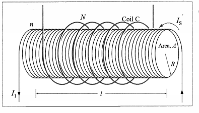
AnswerWe assume the solenoid to be ideal and that all the flux from the solenoid passes through the outer coil $C$. For a steady current Is through the solenoid, the uniform magnetic field inside the solenoid is
$
B =\mu_0 nl \text { s }
$
Then, the magnetic flux through each turn of the coil due to the current in the solenoid is
$
\Phi_{C S}=B A=\left(\mu_0 n l_s\right)\left(\pi R^2\right)
$
Thus, their mutual inductance is
$
M =\frac{N s _{ Cs }}{I_{ S }}=\mu_0 \pi R ^2 nN
$
Equation (2) is true as long as the magnetic field of the solenoid is entirely contained within the cross section of the coil C. Hence, M does not depend on the shape, size, or possible lack of close packing of the coil.
View full question & answer→Question 164 Marks
Explain the concept/phenomenon of mutual induction.###Explain and define mutual inductance of a coil with respect to another coil.###Define the coefficient of mutual induction.
Answer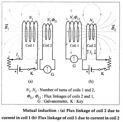
The production of induced emf in a coil due to the change of current in the same coil is called self induction.
In above figure (a), a current $l _1$ in coil 1 sets up a magnetic flux $\Phi_{21}$ through one turn of a neighbouring coil 2, magnetically linking the two coils. Then, the flux through the $N _2$ turns of coil 2, i.e, the flux linkage of coil 2 , is $N _2 \Phi_{21}$.
$N _2 \Phi_{21} \propto I _1$
$\therefore N _2 \Phi_{21}= M _{21} l _1$
where the constant of proportionality, $M _{21}$, is called the coefficient of mutual induction of coil 2 with respect to coil 1 . If the current $I_1$ in coil 1 changes with time, the varying flux linkage induces an emf $e_2$ in coil 2.
$
e_2=-\frac{d}{d t}\left(N_2 \Phi_{21}\right)=-M_{21} \frac{d I_1}{d t}
$
Similarly, if we interchange the roles of the two coils and set up a current $I _2$ in coil 2 [from figure (b)], Then, the flux linkage of $N 1$ turns of coil 1 is $N_1 \Phi_{12}$ and
$N _1 \Phi_{12}= M _{12} I _2$
where $M_{12}$ is the coefficient of mutual induction of coil 1 with respect to coil 2. And, for a varying current $I _2( t )$, the induced emf in coil 1 is
$
e_1=-\frac{d}{d t}\left(N_1 \Phi_{12}\right)=-M_{12} \frac{d I_2}{d t}
$
It can be shown that $M_{21}=M_{12}=M$ (say). So, it is customary to drop the subscripts and write
$
M=\frac{N_2 \Phi_{21}}{I_1}=\frac{N_1 \Phi_{12}}{I_2}
$
Also, from Eqs. (2) and (4),
$
M=\left|\frac{e_2}{d I_1 / d t}\right|=\left|\frac{e_1}{d l_2 / d t}\right|
$
We define mutual inductance using Eq. (5) or Eq. (6).
The mutual inductance or the coefficient of mutual induction of two magnetically linked coils is equal to the flux linkage of one coil per unit current in the neighbouring coil.
OR
The mutual inductance or the coefficient of mutual induction of two magnetically linked coils is numerically equal to the emf induced in one coil (secondary) per unit time rate of change of current in the neighbouring coil (primary). View full question & answer→Question 174 Marks
A solenoid of $1000$ tums is wound with wire of diameter $0.1 \ cm$ and has a self inductance of $2.4 \pi \times 10^{-5} H$. Find $(a)$ the cross $-$ sectional area of the solenoid $(b)$ the magnetic flux through one turn of the solenoid when a current of $3 \ A$ flows through it.
AnswerData: $ N=1000, D=0.1 \ cm , $
$L=2.4 \pi \times 10^{-5} H ,$
$I=3 A, \mu_0=4 \pi \times 10^{-7} H / m$
The number of turns per unit length.
$n =\frac{1}{1 \ mm }=1 \ mm ^{-1}=10^3 m ^{-1}$
and the length of the solenoid,
$I=N D=1000 \times 0.1=100 \ cm =1 m$
$L=\mu_0 n^2 / A$
$(a) $ The area of cross section,
$A =\frac{L}{\mu_0 n^2 l}$
$=\frac{2.4 \pi \times 10^{-5}}{\left(4 \pi \times 10^{-7}\right)\left(10^3\right)^2(1)}$
$=\frac{24 \pi}{4 \pi} \times 10^{-5}$
$=6 \times 10^{-5} m ^2$
$(b)$ Magnetic flux through one turn,
$\Phi_m=B A=\left(\mu_0 n l\right) A$
$=\left(4 \pi \times 10^{-7}\right)\left(10^3\right)(3)\left(6 \times 10^{-5}\right)$
$=72 \pi \times 10^{-9} Wb$
View full question & answer→Question 184 Marks
Determine the magnetic energy stored per unit length of a coaxial cable, represented by two coaxial cylindrical shells of radii a $($inner$)$ and b $($outer$)$, and carrying a current $I$. Hence derive an expression for the self inductance of the coaxial cable of length $I.$
AnswerFigure $(a)$ shows a coaxial cable represented by two hollow, concentric cylindrical conductors along which there is electric current in opposite directions. The magnetic field between the conductors can be found by applying Ampere's law to the dashed path of radius $r(a \oint \vec{B} \cdot \overrightarrow{d l}= B (2 \pi r )= u _0 l$
$\therefore B =\frac{\mu_0 I}{2 \pi} \ldots \ldots \ldots \ldots \ldots \ldots \ldots{(1)}$
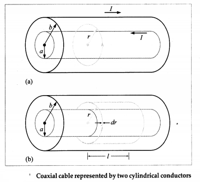
A similar application of Ampere's law for $r>b$ and $r$ The energy density of the magnetic field is
$u _{ m }=\frac{B^2}{2 \mu_0}$
Therefore, substituting for $B$ from Eq. $(1)$ into Eq. $(2)$, the magnetic energy stored in a cylindrical shell of radius $r$, thickness $d r$ and length $I$ is
$d U_m=u_m d V=u_m(2 \pi r \cdot d r \cdot I)$
$\therefore d U_m=\frac{\mu_0}{8 \pi^2} \cdot\left(\frac{l}{r}\right)^2(2 \pi r l \cdot d r)=\left(\frac{\mu_0}{4 \pi}\right) I^2 l \cdot \frac{d r}{r}$
Thus, the total energy of the magnetic field in a length $l$ of the cable is
$U_{ m } =\int_a^b d U=\left(\frac{\mu_0}{4 \pi}\right) I^2 l \int_a^b \frac{d r}{r}$
$\therefore U_{ m } =\left(\frac{\mu_0}{4 \pi}\right) I^2 l \log _a \frac{b}{a}$
MaharashtraBoardSolutions.Guru
Hence, the magnetic energy stored per unit length in the coaxial cable is
$\frac{U_{ m }}{l}=\left(\frac{\mu_0}{4 \pi}\right) I^2 \log _e \frac{b}{a}$
If $L$ is the self inductance of the coaxial cable of length $l$,
$U_{ m }=\frac{1}{2} L I^2$
Equating the right hand sides of Eqs. $(4)$ and $(6),$
$\frac{1}{2} L I^2=\left(\frac{\mu_0}{4 \pi}\right) I^2 l \log _e \frac{b}{a}$
$\therefore L=\left(\frac{\mu_0}{4 \pi}\right) 2 l \log _{\ell} \frac{b}{a}$ View full question & answer→Question 194 Marks
Obtain an expression for the energy density of a magnetic field.
AnswerConsider a short length ; near the middle of a long, tightly wound solenoid, of crosssectional area $A$, number of turns per unit length $n$ and carrying a steady current $I$. For such a solenoid, the magnetic field is approximately uniform everywhere inside and zero outside. So, the magnetic energy $U_m$ stored by this length I of the solenoid lies entirely within the volume Al.
The magnetic field inside the solenoid is
$
B =\mu_0 nl
$
and if $L$ be the inductance of length I of the solenoid,
$
L=\mu_0 n^2 \mid A
$
The stored magnetic energy,
$
U _{ m }=\frac{1}{2} LI ^2
$
and the energy density of the magnetic field (energy per unit volume) is
$
u_{ m }=\frac{U_{ m }}{A l}=\frac{1}{2} \frac{L I^2}{A l}
$
Substituting for $L$ from Eq. (2),
$
\begin{aligned}
u_{ m } & =\frac{1}{2} \frac{\mu_0 n^2 l A l^2}{A l}=\frac{1}{2} \mu_0 n^2 I^2 \\
\therefore u_{ m } & =\frac{1}{2} \mu_0\left(\frac{B}{\mu_0 I}\right)^2 I^2=\frac{B^2}{2 \mu_0}
\end{aligned}
$
Equation (6) gives the magnetic energy density in vacuum at any point in a magnetic field of induction $B$, irrespective of how the field is produced.
[Note : Compare Eq.(6) with the electric energy density in vacuum at any point in an electric field of intensity
$e, u_e=\frac{1}{2} \varepsilon_0 e^2$. Both $u_e$ and $u_m$ are proportional to the square of the appropriate field magnitude.]
View full question & answer→Question 204 Marks
Derive an expression for the self inductance of a narrow air $-$ cored toroid of circular cross section.
AnswerConsider a narrow air $-$ cored toroid of circular cross section of radius $r_r$ central radius $R$ and number of turns $N$.
So that, assuming $r \| R$, the magnetic field in the toroidal cavity is considered to be uniform, equal to
$B =\frac{\mu_0 N I}{2 \pi R}=\mu_0 nl$
where $n =\frac{N}{2 \pi R}$ is the number of turns of the wire $2 nR$ per unit length.
The area of cross section, $A=\pi r^2$.
The magnetic flux through one tum is
$\Phi_m=B A=\mu_0 n \mid A$
Hence, the self inductance of the toroid,
$L =\frac{N \Phi_{ m }}{I}=(2 \pi Rn ) \mu_0 n A $
$=\mu_0 2 \pi Rn ^2 A =\mu_0 n ^2 V$
$=\frac{\mu_0 N^2 r^2}{2 R} \ldots \ldots . . . . .$
where $V=2 \pi R A$ is the volume of the toroidal cavity.
Equation $(3)$ or $(4)$ gives the required expression.
View full question & answer→Question 214 Marks
Obtain an expression for the self inductance of a solenoid.
AnswerConsider a long air-cored solenoid of length $Z$, diameter $d$ and $N$ turns of wire. We assume that the length of the solenoid is much greater than its diameter so that the magnetic field inside the solenoid may considered to be uniform, that is, end effects in the solenoid can be ignored. With a steady current $I$ in the solenoid, the magnetic field within the solenoid is $B =\mu_0 nl$ (1) where $n=N / 1$ is the number of turns per unit length. So the magnetic flux through one turn is
$
\Phi_m=B A=\mu_0 n \mid A
$
Hence, the self inductance of the solenoid,
$L =\frac{N T _{ m }}{I}=( n l ) \mu_{0 O } A =\mu_0 n ^2 IA =\mu_0 n ^2 V$
$=\mu_0 n^2 \mid \frac{\pi d^2}{4}$
where $V=$ IA is the interior volume of the solenoid. Equation (3) or (4) gives the required expression.
[Note: It is evident thatthe self inductance of a long solenoid depends only on its physical properties - such as the number of turns of wire per unit length and the volume, and not on the magnetic field or the current. This is true for inductors in general.] .
View full question & answer→Question 224 Marks
Derive an expression for the energy stored in the magnetic field of an inductor.###Derive an expression for the electrical work done in establishing a steady current in a coil of self inductance L.
AnswerConsider an inductor of sell inductance $L$ connected in a circuit When the circuit is dosed, the current in the circuit increases and so does the magnetic flux linked with the coil At any instant the magnitude of the induced emf is
$
e = L \frac{d i}{d t}
$
The power consumed in the inductor is
$
P = ei = L \frac{d i}{d t} \cdot i
$
[Alternatively, the work done in moving a charge dq against this emf e is
$
dw = edq = L \frac{d i}{d t} \cdot dq = Li \cdot di \left(\because \frac{d q}{d t}= i \right)
$
This work done is stored in the magnetic field of the inductor. $d w=d u$.
The total energy stored In the magnetic field when the current increases from 0 to I In a time interval from 0 to $t$ can be determined by integrating this expression :
$
U _{ m }=\int_0^t P d t=\int_0^I L i d i=L \int_0^I i d i=\frac{1}{2} L I^2
$
which is the required expression for the stored magnetic energy.
[Note: Compare this with the electric energy stored in a capacitor, $U _{ e }=\frac{1}{2} CV ^2$ ]
View full question & answer→Question 234 Marks
Explain and define the self inductance of a coil. Define the coefficient of self induction.
AnswerWhen the current through a coil goes on changing, the magnetic flux linked with the coil also goes on changing.
The magnetic flux $\left(N \Phi_m\right)$ linked with the coil at any instant is directly proportional to the current $(I)$ through the coil at that instant.
$N \Phi_m \propto 1$
$\therefore N \Phi_m= LI$
where $L$ is a constant, dependent on the geometry of the coil, called the self inductance or the coefficient, of self induction of the coil.
The self $-$ induced emf in the coil is
$e=-\frac{d N \Phi_{ m }}{d t}=-\frac{d}{d t}(L l)=-L \frac{d I}{d t}$
In magnitude,
$e =L \frac{d l}{d t}$
$\therefore L =\frac{e}{d I / d t}$
Definition : The self inductance or the coefficient of self induction of a coil is defined as the emf induced in the coil per unit time rate of change of current in the same coil. $OR\ ($using $L= \left.N \Phi_m / l\right),$
the self inductance of a coil is the ratio of magnetic flux linked with the coil to the current in it.
View full question & answer→Question 244 Marks
Explain the concept of self induction.
AnswerConsider an isolated coil or circuit in which there is a current I. The current produces a magnetic flux linked with the coil.
The magnetic flux linked with the coil can be changed by varying the current in the coil itself, e.g., by breaking and closing the circuit. This produces a self-induced emf in the coil, called a back emf because it opposes the change producing it. It sets up an induced current in the coil itself in the same direction as the original current opposing its decrease when the key $K$ is suddenly opened. When the key $K$ is closed, the induced current is opposite to the conventional current, opposing its increase.
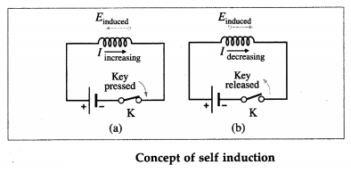
When the current through a coil changes continuously, e.g., by a time-varying applied emf, the magnetic flux linked with the coil also goes on changing.
The production of induced emf in a coil, due to the changes of current in the same coil, is called self induction. View full question & answer→Question 254 Marks
A solid conducting plate swings like a pendulum about a pivot into a region of uniform magnetic field, as shown in the diagram. As it enters and leaves the field, show and explain the directions of the eddy current induced in the plate and the force on the plate.
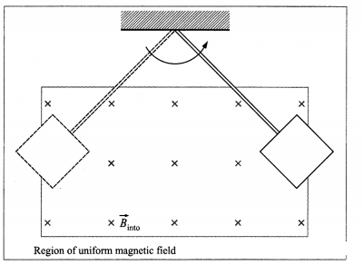
AnswerFigure shows the eddy currents in the conducting plate as it enters and leaves the magnetic field. In both cases, it experiences a force $\vec{F}$ opposing its motion. As the plate enters from the left, the magnetic flux through the plate increases. This sets up an eddy current in the anticlockwise direction, as shown. Since only the right-hand side of the current loop is inside the field, by Fleming's right hand rule (FRH rule), an unopposed force acts on it to the left. There is no eddy current once the plate is completely inside the uniform field. When the plate leaves the field on the right, the decreasing flux causes an eddy current in the clockwise direction. The damping magnetic force on the current is to the left, further slowing the motion.
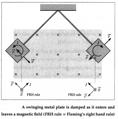
The eddy current in the plate results in mechanical energy being dissipated as thermal energy. Each time the plate enters and leaves the field, a part of its mechanical energy is transformed into thermal energy. After a few swings, the mechanical energy becomes zero and the motion comes to a stop with the warmed-up plate hanging vertically. View full question & answer→Question 264 Marks
Describe in brief an experiment to demonstrate that eddy currents oppose the cause producing them.
AnswerApparatus: A strong electromagnet; two thick copper discs ( $4^n$ dia, $\frac{1}{4}^n$ thick), each attached to a rod about 30 " long. One of the discs has several vertical slots, about $80 \%$ of the way up. The pendulums can be suspended from a lab stand by a pivot mount and made to oscillate between closely-spaced pole pieces of the electromagnet.
Experiment: When the electromagnet is not turned on, both the pendulums swing freely with some damping due to air resistance. When the electromagnet is turned on, the slotted pendulum still swings, although a little more damped, but the solid pendulum practically stops dead between the pole pieces of the magnet immediately.
Conclusion: As the pendulums enter or exit the magnetic field, the changing magnetic flux sets up eddy currents in the discs. The sense of the eddy currents is so as to produce a torque that opposes the rotation of the discs about their pivot. This opposing torque produces a breaking action, damping the oscillations.
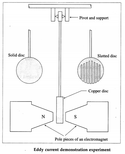
In the case of the solid disc, the continuous volume of the disc offers large unbroken path to the swirling electrons. Thus, the eddy current builds up to a large magnitude. The thicker the disc, the larger is the eddy current and, consequently, the larger the damping.
In the case of the slotted disc, the vertical slots do not allow large eddy current and, consequently, the damping is small. View full question & answer→Question 274 Marks
Find an expression for the power expended in pulling a conducting loop out of a magnetic field.
AnswerWhen an external agent produces a relative motion between a conducting loop and an external magnetic field, a magnetic force resists the motion, requiring the applied force to do positive work. The work done is transferred to the material of the loop as thermal energy because of the electrical resistance of the material to the current that is induced by the motion.
Proof : Consider a rectangular wire loop ABCD of width I, with its plane perpendicular to a uniform magnetic field of induction $\vec{B}$. The loop is being pulled out of the magnetic field at a constant speed $v$, as shown in below figure (a).
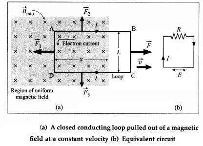
At any instant, let $x$ be the length of the part of the loop in the magnetic field. As the loop moves to the right through a distance $d x=v d t$ in time $d_t$ the area of the loop inside the field changes by $d A=I d x=$ lvdt. And, the change in the magnetic flux $d \Phi_m$ through the loop is
$
d \Phi_m=B d A=\text { Blvdt }
$
Then, the time rate of change of magnetic flux is
$
\frac{d \Phi_{ m }}{d t}=\frac{B l w d t}{d t}=B \mid V
$
By Faraday's second law, the magnitude of the induced emf is
$
| e |=\frac{d \Phi_{ m }}{d t}= B \mid v
$
Due to the motion of the loop, the tree electrons (charge, e) in the wire inside the field experience Lorentz force $e \vec{v} \times \vec{B}$. In the wire PQ this force moves the Free electrons $1 mm P$ to $Q$ making them travel in the anticlockwise sense around the 1oop. Therefore, the induced conventional current $I$ is in the clockwise sense, as shown.
From figure (b) shows the equivalent circuit of the loop, where the induced emf $e$ is a distributed emf and $R$ is the total resistance of the loop.
$
\therefore I=\frac{|e|}{R}=\frac{B l v}{R}
$
Now, a straight current carrying conductor of length $L$ in a magnetic held experiences a torce $\vec{F}=I \vec{L} \times \vec{B}$
whose direction can be found using Fleming's Left hand rule.
Accordingly, forces $\vec{F}_2$ and $\vec{F}_3$ on wires $AH$ and $CD$, respectively, are equal in magnitude (= 1.8), opposite in direction and have the same line of action-Hence, they balance each other. There is no torce on the wire $B C$ as it hes outside the field.
The force $\vec{F}_1$ on the wire AD has magnitude $F_1=\| B$ and $ls$ directed towards the left. To move the loop with constant velocity $\vec{v}$, an external force $\vec{F}=-\vec{F}_1$ must be applied. Therefore, in magnitude,
$
\begin{aligned}
|F| & =F_1=l l B=\frac{B l v}{R} \cdot l B \\
& =\frac{B^2 l^2 v}{R}
\end{aligned}
$
Because $B, I$ and $R$ are constants a force of constant magnitude $F$ is required to move the loop at constant speed $v$.
Thus, the power or the rate of doing work by the external agent is
$
P =\vec{F} \cdot \vec{v}= Fv =\frac{B^2 l^2 v^2}{R}
$ View full question & answer→Question 284 Marks
A motor draws more current when it starts than when it runs at its full (i.e., operating) speed. Explain.###When a pump or refrigerator (or other large motor) starts up, lights in the same circuit dim briefly.
AnswerThe back emf is effectively the generator output of a motor, and is proportional to the angular velocity co of the motor. Hence, when the motor is first turned on, the back emf is zero and the coil receives the full input voltage. Thus, the motor draws maximum current when it is first turned on. As the motor speeds up, the back emf grows, always opposing the driving emf, and reduces the voltage across the coil and the amount of current it draws. This explains why a motor draws more current when it first comes on, than when it runs at its normal operating speed.
The effect is noticeable when a high power motor, like that of a pump, refrigerator or washing machine is first turned on. The large initial current causes the voltage at the outlets in the same circuit to drop. Due to the IR drop produced in feeder lines by the large current drawn by the motor, lights in the same circuit dim briefly.
[Note : A motor is designed to run at a certain speed for a given applied voltage. A mechanical overload on the motor slows it down appreciably. If the rotation speed is reduced, the back emf will not be as high as designed for and the current will increase. At too low speed, the large current can even burn its coil. On the other hand, if there is no mechanical load on the motor, its angular velocity will increase until the back emf is nearly equal to the driving emf. Then, the motor uses only enough energy to overcome friction.]
View full question & answer→Question 294 Marks
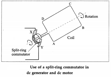
How does a dc generator differ from an ac generator?
AnswerA dc generator is much like an ac generator, except that the slip rings at the ouput are replaced by a split-ring commutator, just as in a dc motor.
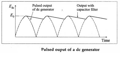
The output of a dc generator is a pulsating dc as shown in Fig. 12.22. For a smoother output, a capacitor filter is connected in parallel with the output (see below figure for reference).
View full question & answer→Question 304 Marks
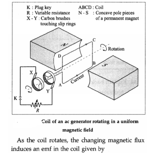
Briefly describe the construction of a simple ac generator. Obtain an expression for the emf induced in a coil rotating with a uniform angular velocity in a uniform magnetic field. Show graphically the variation of the emf with time (t). OR Describe the construction of a simple ac generator and explain its working.
AnswerConstruction : A simplified diagram of an ac generator is shown in below figure 12.18. It consists of many loops of wire wound on an armature that can rotate in a magnetic field. When the armature is turned by some mechanical means, an emf is generated in the rotating coil.
Consider the coil to have $N$ turns, each of area $A$, and rotated with a constant angular speed $\omega$ - about an axis in the plane of the coil and perpendicular to a uniform magnetic field $\vec{B}$, as shown in the figure. The frequency of rotation of the coil is $f=\omega / 2 \pi$.
Working : The angle 9 between the magnetic field $\vec{B}$ and the area of the coil $\vec{A}$ at any instant $t$ is $\theta=\omega t$ (assuming $\theta=0^{\circ}$ at $t =0$ ). At this position, the magnetic flux through the coil is
$
\Phi_{ m }=N \vec{B} \cdot \vec{A}= NBA \cos \theta= NBA \cos \omega t
$
$
\begin{aligned}
e & =-\frac{d \Phi_{ m }}{d t}=-\frac{d}{d t}(N B A \cos \omega t) \\
& =-N B A \frac{d}{d t}(\cos \omega t)=N B A \omega \sin \omega t
\end{aligned}
$
$\therefore e = e _0 \sin \omega t$, where $e _0=$ NBAw.
Therefore the induced emf varies as sin cot and is called sinusoidally alternating emf. In one rotation of the coil, sin cot varies between +1 and -1 and hence the induced emf varies between $+e_0$ and $-e_0$. The maximum value $e_0$ of an alternating emf is called the peak value or amplitude of the emf.
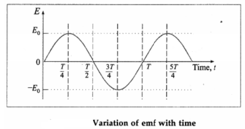
The sinusoidal variation of emf with time t is shown in above figure. The emf changes direction at the end of every half rotation of the coil. The frequency of the alternating emf is equal to the frequency/of rotation of the coil. The period of the alternating emf is T = 1f
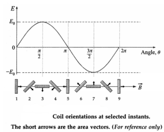
Imagine looking at the coil of the ac generator from the slip rings along the rotation axis in Fig. 12.18. The magnetic flux, rate of change of flux and sign of the induced emf are shown in the table below for the different orientations of the coil as in below figure.Coil orientation | Flux $\Phi_m$ | $d \Phi_{ m } / dt$ | Induced emf |
1 | Positive maximum | Momentarily zero (constant flux) | Zero |
2 | Positive | Decreasing (negative) | Positive |
3 | Zero | Decreasing (negative) | Positive |
4 | Negative | Decreasing (negative) | Positive |
5 | Negative Maximum | Momentarily zero (constant flux) | Zero |
6 | Negative | Increasing (positive) | Negative |
7 | Zero | Increasing (positive) | Negative |
8 | Positive | Increasing (positive) | Negative |
9 | Return to positive maximum | Momentarily zero (constant flux) | Zero |
View full question & answer→Question 314 Marks
In the experiment to investigate the phenomenon of electromagnetic induction for a magnet swinging through a coil, show that the peak induced emf is directly proportional to the speed of the magnet $($or show that the peak induced emf is directly proportional to the angular amplitude and inversely proportional to the time period$).$
AnswerIn the experiment, a magnet is swung through a coil in a radius $R$.
The angular position $\theta$ of the magnet is measured from the vertical, the mean position of the swing.
The angular amplitude is $\theta_0$.
The kinetic energy of the system is $\frac{1}{2} I \omega^2$ and the potential energy $($relative to the lowest position of the magnet$)$ is $M g R(1-\cos \theta)$,
where $M$ is mass of the system. Conservation of energy gives, for small $\theta$,
$\frac{1}{2} I\left(\frac{d \theta}{d t}\right)^2+\frac{1}{2} M g R \theta^2=\text { constant }$
Differentiating this,
we get $\frac{d^2 \theta}{d t^2}+\frac{M g R}{I} \theta=0$
i.e., the motion is approximately simple harmonic with a time period
$T=2 \pi \sqrt{\frac{I}{M g R}}$
$\therefore \theta=\theta_0 \sin \frac{2 \pi}{T} t \text {}$
$\therefore \omega=\frac{d \theta}{d t}=\frac{2 \pi}{T} \theta_0 \cos \frac{2 \pi}{T} t$
$\therefore v_{\max }=R \omega_{\max }=\frac{2 \pi}{T} \theta_0 R$
The magnitude of the peak induced emf,
$\left|e_0\right|=\frac{d \Phi_{ m }}{d t}=\frac{d \Phi_{ m }}{d \theta} \frac{d \theta}{d t}=\frac{d \Phi_{ m }}{d \theta}\left(2 \pi R \frac{\theta_0}{T}\right)=\frac{d \Phi_{ m }}{d \theta} \cdot v_{\max }$
as required.
The rate of change of flux through the coil is essentially proportional to the velocity of the magnet as it passes through the coil.
By choosing different amplitudes of oscillation of the magnet, we can alter this velocity.
View full question & answer→Question 324 Marks
In the experiment to investigate the phenomenon of electromagnetic induction for a magnet swinging through a coil, relate the graphical representations $($flux$-$time and voltage$-$time$)$ with the motion of the magnet.
AnswerIn the demonstration of a magnet swinging through a coil, a voltage is induced in the coil as the magnet swings through it. For the discussion, we assume the length of the magnet to be smaller $($about half$)$ than the length of the coil and the North pole of the magnet swings into the coil from the left. $($The polarity of the induced voltage pulse depends on the polarity of the magnet.$)$
We take the magnetic flux linked with the coil to be nearly zero when the magnet is high up away from the coil. As the magnet moves through it the coil and recedes, the magnetic field through the coil increases to its maximum and then decreases. There is a substantial magnetic field at the coil only when it is very near the magnet. Moreover, the speed of the magnet is maximum when it is at the centre of the coil, since it is then at the mean position of its oscillation. Thus the magnetic field changes quite slowly when the magnet is far away and rapidly as it approaches the coil, from figure $(a).$
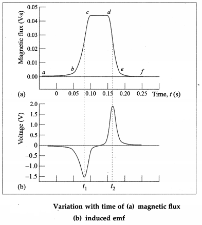
The flux through the coil increases as the north pole approaches the left end of the coil, and reaches a maximum when the magnet is exactly midway in the coil, as shown by the portion be in from figure $(a).$ By Lenz’s law, the induced emf will produce a leftward flux that will seek to oppose the increasing magnetic flux of the magnet through the coil.
The interval cd, when the flux is maximum but remains constant and induced emf is zero, corresponds to the situation where the magnet is wholly inside the coil.
Once the magnet swings past the centre of the coil, the flux through the coil starts to decrease$-$the interval de. To reinforce the decreasing flux of the magnet through the coil, a rightward flux is now induced, thereby flipping the polarity of the induced emf.
If we use a coil that is shorter than the magnet, the time interval cd for which the induced emf remains zero would have been shorter. The times $f_1$ and $f_2$ in from figure $(a)$ are the points of inflection of the curve, and in from figure $(b)$ are obviously the minimum and maximum of the induced emf, respectively. The sequence of two pulses, one negative and one positive, occurs during just half a cycle. On the return swing of the magnet, they are repeated in the same order. View full question & answer→Question 334 Marks
Briefly describe with necessary diagrams the experimental setup to investigate the phenomenon of electromagnetic induction for a magnet swinging through a coil.
AnswerApparatus: A permanent magnet is mounted at the centre of the arc of a semicircular aluminium frame of radius $50 \ cm.$ The whole frame is pivoted at its centre and can oscillate freely in its plane, from figure $(a).$ Movable weights $m_1$ and $m_2$ on the radial arms of the frame can be symmetrically positioned to adjust the period of oscillation from about $1.5s$ to $3s.$ The magnet can freely pass through a copper coil of about $10000$ turns.
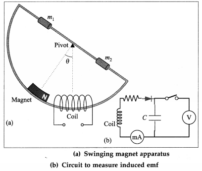
When the magnet swings through and out of the coil, the magnetic flux through the coil changes, inducing an emf. The amplitude of the swing can be read from the graduations on the arc. Since the induced emf will be small, it may be measured by connecting the terminals of the coils to a $\text{CRO} ($cathode$-$ray oscilloscope, or they may be connected to a $100 pF$ capacitor through a diode, from figure $(b),$ and the voltage across the capacitor is measured. The resistor in series with the diode helps to adjust the capacitor charging time $( = RC).$
$[$Note : Real$-$time graphs can be captured using a datalogger connected to a computer. The datalogger uses rotary motion, voltage and magnetic field sensors to measure the angle, the induced voltage and the magnetic flux, respectively.$]$
View full question & answer→Question 344 Marks
A cycle wheel with $10$ spokes, each of length $0.5 m$, is moved at a speed of $18 \ km / h$ in a plane normal to the Earth's magnetic induction of $3.6 \times 10^{-5} T$. Calculate the emf induced between
$(i)$ the axle and the rim of the cycle wheel
$(ii)$ ends of a single spoke and ten spokes.
AnswerData : $ r = I =0.5 m , v =18 \ km / h =\frac{18000}{3600}=5 m / s ,$
$B=3.6 \times 10^{-5} T$
$v=\omega r=(2 \pi f) r$
$\therefore f=\frac{v}{2 \pi r}=\frac{5}{2 \pi \times 0.5}$
$=\frac{5}{\pi} Hz$
The induced emf across each spoke,
$|e| =\frac{d \Phi_{ m }}{d t}=\frac{d}{d t}(A B)$
$=B \frac{d A}{d t}=B\left(\pi r^2 f\right)$
$\therefore|e| =3.6 \times 10^{-5} \times \pi \times(0.5)^2 \times \frac{5}{\pi}$
$ =4.5 \times 10^{-5} V$
Since the spokes have common ends $($the axle and wheel rim$),$ they are connected in parallel.
Hence,
the emf induced between the end of a single spoke and the other common end of ten spokes is also $4.5 \times 10^{-5} V$.
Since the total emf of this parallel combination of identical emfs $e$ is equal to a single emf $e_{\text {, }}$ the emf induced between the axle and wheel rim is equal to $4.5 \times 10^{-5} V$.
View full question & answer→Question 354 Marks
A metal rod $1 / \sqrt{\pi} m$ long rotates about one of its ends in a plane perpendicular to a magnetic field of induction $4 \times 10^{-3} T$. Calculate the number of revolutions made by the rod per second if the emf induced between the ends of the rod is $16 m V$.
AnswerData : $r=I=\frac{1}{\sqrt{\pi}} m , B=4 \times 10^{-3} T _{ s }| e |=16 mV =16 \times 10^{-3} V$
In one rotation, the rod traces out a circle of radius $Z_{\text {, i.e., }}$ an area, $A=\pi l^2$ Therefore, the time rate at which the rod traces out the area is
$
\frac{d A}{d t}=\text { frequency of rotation } \times A=f A
$
$\therefore$ The induced emf,
$
\begin{aligned}
|e| & =\frac{d \Phi_{ m }}{d t}=\frac{d}{d t}(A B)=B \frac{d A}{d t}=B f A \\
\therefore f & =\frac{|e|}{B A}=\frac{|e|}{B \pi l^2} \\
& =\frac{16 \times 10^{-3}}{\left(4 \times 10^{-3}\right)\left[\pi\left(\frac{1}{\sqrt{\pi}}\right)^2\right]} \\
& =\frac{16 \times 10^{-3}}{\left(4 \times 10^{-3}\right)\left(\pi \times \frac{1}{\pi}\right)}=4 rps
\end{aligned}
$
View full question & answer→Question 364 Marks
Determine the motional emf induced in a straight conductor rotating in a uniform magnetic field with constant angular velocity.
AnswerSuppose a rod of length 1 is rotated anticlockwise, around an axis through one end and perpendicular to its length, in a plane perpendicular to a uniform magnetic field of induction $\vec{B}_t$ as shown in below figure; $\vec{B}$ points into the page. Let the constant angular speed of the rod be $\omega$.
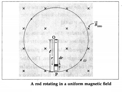
Consider an infinitesimal length element $d r$ at a distance $r$ from the rotation axis. In one rotation, the area traced by the element is $d A=2 \pi r d r$. Therefore, the time rate at which the element traces out the area is
$
\frac{d A}{d t}=\text { frequency of rotation } \times d A=f d A
$
where $f=\frac{\omega}{2 \pi}$ is the frequency of rotation.
$
\therefore \frac{d A}{d t}=\frac{\omega}{2 \pi}(2 \pi r d r)=\omega r d r
$
Therefore, the magnitude of the induced emf in the element is
$
|d e|=\frac{d \Phi_{ m }}{d t}=B \frac{d A}{d t}= B \omega r d r
$
Since the emfs in all the elements of the rod will be in series, the total emf induced across the ends of the rotating rod is
$
| e |=\int d e=\int_0^l B \omega r d r=B \omega \int_0^l r d r=B \omega \frac{\ell^2}{2}
$
For anticlockwise rotation in $B$ pointing into the page, the pivot point $O \vec{B}$ is at a higher potential.
[Note : To understand the polarity of the emf across the ends of the rod, imagine that the rod slides along a wire that forms a circular arc MPN of radius/, as shown below. Assume that the resistor $R$ furnishes all of the resistance in the closed loop. As 9 increases, so does the inward flux through the loop due to $\vec{B}$.
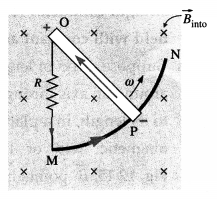
To counteract this increase, the magnetic field due to the induced current must be directed out of the page in the region enclosed by the loop. Therefore, the current in the loop POMP circulates anticlockwise with the motional emf directed from P to O.] View full question & answer→Question 374 Marks
Determine the motional emf induced in a straight conductor moving in a uniform magnetic field with constant velocity on the basis of Lorentz force.
AnswerConsider a straight rod or wire PQ of length $I$, lying wholly in a plane perpendicular to a uniform magnetic field of induction $B$, as shown in below figure; $\vec{B}$ points into the page.
Suppose an external agent moves the wire to the right with a constant velocity $\vec{v}$ perpendicular to its length and to $\vec{B}$. The free electrons in the wire experience a Lorentz force $\vec{F}(=q \vec{v} \times \vec{B})$.
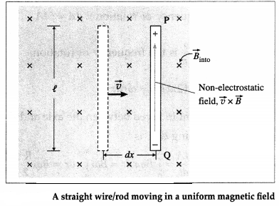
According to the right-hand rule for cross products, the Lorentz force on negatively charged electrons is downward. The Lorentz force $\vec{F}$ moves the free electrons in the wire from $P$ to $Q$ so that $P$ becomes positive with respect to $Q$. Thus, there will be a separation of the charges to the two ends of the wire until an electric field builds up to oppose further motion of the charges.
In moving the electrons a distance I along the wire, the work done by the Lorentz force is $W = Fl =( qvB \sin \theta) I = qvBl$
since the angle between $\vec{v}$ and $\vec{B}, \theta=90^{\circ}$. Since electrical work done per unit charge is emf, the induced emf in the wire is
$
e=\frac{W}{q}=v B \mid
$
Alternatively, the electric field due to the separation of charges is $\vec{F} / q=\vec{v} \times \vec{B}$. Since $\vec{v}$ is perpendicular to $B$, the magnitude of the field $=v B$.
Electric field $=\frac{\text { p.d. }(e) \text { between } P \text { and } Q }{\text { distance } PQ (l)}$
Therefore, the p.d. or emf induced in the wire $P Q$ is $e=v B$ I View full question & answer→Question 384 Marks
Determine the motional emf induced in a straight conductor moving in a uniform magnetic field with constant velocity.
AnswerConsider a straight wire AB resting on a pair of conducting rails separated by a distance I lying wholly in a plane perpendicular to a uniform magnetic field $\vec{B}$. $\vec{B}$ points into the page and the rails are stationary relative to the field and are connected to a stationary resistor $R$.
Suppose an external agent moves the rod to the right with a constant speed v, perpendicular to its length and to $\vec{B}$. As the rod moves through a distance $d x=$ vdt in time $d t$, the area of the loop $ABCD$ increases by $dA = Idx = lv dt$.
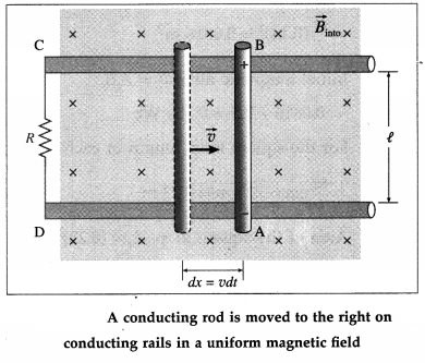
Therefore, in time $dt _{\text {, }}$ the increase in the magnetic flux through the loop,
$
d \Phi_m=B d A=\text { Blvdt }
$
By Faraday's law of electromagnetic induction, the magnitude of the induced emf
$
e =\frac{d \Phi_{ m }}{d t}=\frac{B l v d t}{d t}= Blv
$ View full question & answer→Question 394 Marks
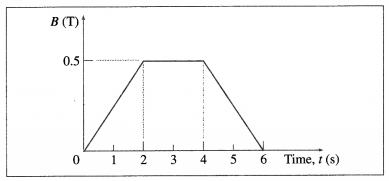
The magnetic field through a wire loop, of radius $12 \ cm$ and resistance $8.5 \Omega ,$ changes with time as shown in the graph below. The magnetic field is uniform and perpendicular to the plane of the loop. Calculate the $\text{emf}$ induced in the loop as a function of time. Hence, find the induced emf in the time interval $(a) t = 0$ to $t = 2 s\ (b) t = 2 s$ to $t = 4s\ (c) t = 4s$ to $t = 6s.$
Answer$r=0.12 m ,$
$R =8.5 \Omega$
$e =-\frac{d \Phi_{ m }}{d t}$
$=-\frac{d}{d t}(B A \cos \theta)$
$ =-A \frac{d B}{d t}=-\pi r^2 \frac{d B}{d t}$
$ =-(3.142)(0.12)^2 \frac{d B}{d t}$
$=-4.524 \times 10^{-2} \frac{d B}{d t}$
This is the $\text{emf}$ induced in the loop as a function of time.
$\frac{d B}{d t}$ is the slope of the $B-t$ graph
$(a)$ In the time interval $t=0$ to $t=2 s$,
slope $=+\frac{0.5 T }{2 s }=+\frac{1}{4} T / s$
$\therefore e=-4.524 \times 10^{-2}\left(+\frac{1}{4}\right)=-1.131 V$
$(b)$ In the time interval $t=2 s$ to $t=4 s$,
slope $=0$
$\therefore e=0 V$
$(c)$ In the time interval $t=4 s$ to $t=6 s$,
slope $=\frac{0-0.5 T }{2 s }=-\frac{1}{4} T / s$
$\therefore e=-4.524 \times 10^{-2}\left(-\frac{1}{4}\right)$
$=1.131 V$
View full question & answer→Question 404 Marks
A wire $88 \ cm$ long is bent into a circular loop and kept with its plane perpendicular to a magnetic field of induction $2.5 Wb / m ^2$. Within $0.5$ second, the coil is changed to a square and the magnetic induction is increased by $0.5 Wb / m ^2$. Calculate the emf induced in the wire.
AnswerData: $I=88 \ cm , B_i=2.5 Wb / m ^2,$
$ B _f=3 Wb / m ^2, \Delta t =0.5 s$
For the circular loop, $1=2 \pi r$
$\therefore r=\frac{l}{2 \pi}=\frac{88}{2 \times(22 / 7)}=14 \ cm =0.14 m$
Area of the circular loop, $A_i=\pi r^2$
$=\frac{22}{7}(0.14)^2=0.0616 m ^2$
Initial magnetic flux $\Phi_i=A_i B_i$
$=0.0616 \times 2.5=0.154 Wb$
For the square loop, length of each side
$=\frac{88}{4} \ cm =22 \ cm =0.22 m 4$
Area of the square loop, $A_f=(0.22)^2$
$=0.0484 m ^2$
$\therefore \text { Final magnetic flux } \Phi_f=A_f B_f$
$=0.0484 \times 3=0.1452 Wb$
$\text { Induced emf, e }=-\frac{\Phi_r-\Phi_1}{\Delta t}$
$=\frac{\Phi_1-\Phi_r}{\Delta t}$
$\therefore e =\frac{0.154-0.1452}{0.5}$
$=8.8 \times 10^{-3} \times 2$
$=1.76 \times 10^{-2} V$
View full question & answer→Question 414 Marks
A rectangular coil of length $0.5 m$ and breadth $0.4 m$ has resistance of $5 \Omega$. The coil is placed in a magnetic field of induction $0.05 T$ and its direction is perpendicular to the plane of the coil. If the magnetic induction is uniformly reduced to zero in 5 milliseconds, find the emf and current induced in the coil.
AnswerData : I $=0.5 m , b=0.4 m , R=5 \Omega, B=0.05 T _{ f } B _f=0, dt =5 \times 10^{-3} s$
Area of the coil, $A = lb =0.5 \times 0.4=0.2 m ^2$
Initial magnetic flux, $\Phi_i=A_i$
$
=0.02 \times 0.05=0.01 Wb
$
Final magnetic flux, $\Phi_f=0\left(\because B_f=0\right)$
$\therefore$ The induced emf, $e=-\frac{d \Phi}{d t}=\frac{-\left(\Phi_1-\Phi_1\right)}{d t}$
$
=-\frac{(0-0.01)}{5 \times 10^{-3}}=2 V
$
$\therefore$ The induced current, $I=\frac{e}{R}=\frac{2}{5}=0.4 A$
View full question & answer→Question 424 Marks
Explain how Lenz's law is incorporated into Faraday's second law of electromagnetic induction by introducing a minus sign.
AnswerConsider a conducting loop of area A in a uniform external magnetic field $\vec{B}$ with its plane perpendicular to the field, i.e, its area vector $\vec{A}$ is parallel to $\vec{B}$, from below figure. We choose the x-axis along $\vec{B}$ so that $\vec{B}=B \hat{i}$ and $\vec{A}=A \hat{i}$.
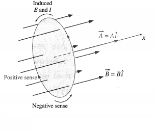
Suppose the magnitude of the magnetic induction increases with time. Then, $\vec{A}$ remaining constant, the induced emf by Faraday-Lenz's second law of electromagnetic induction is $e =-\frac{d F _{ m }}{d t}=-\frac{d}{d t}(B A)=-A \frac{d B}{d t}$
Since we have assumed that $B$ is increasing with time, $d B / d t$ is a positive quantity. Also, $A=$ $|\vec{A}|$ is positive by definition. Hence, the right hand side of Eq. (1) is a negative quantity.
The right hand rule for area vector fixes the positive sense of circulation around the loop as the clockwise sense. Then, by Lenz's law the induced current in the loop is in the anticlockwise sense. The sense of the induced emf is the same as the sense of the current it drives. With the clockwise sense fixed as positive, the anticlockwise sense of the induced current is negative. Hence, the sense of e is also negative. That is, the left hand side of Eq. (1) is indeed a negative quantity. Thus, introducing a minus sign in Faraday's second law incorporates lenz's law into Faraday's law. View full question & answer→Question 434 Marks
State an expression for the magnetic flux through a loop of finite area A inside a uniform magnetic field $\vec{B}$. Hence discuss Faraday's second law, given that the magnetic flux varies with time.
AnswerConsider a conducting loop of finite area A, situated in a uniform magnetic field $\vec{B}$. We choose the direction of the area vector $\vec{A}$ that is closest to the magnetic field. For the area vector in below figure, the fingers of the right hand must be turned in the sense of the arrow on the contour of the loop.
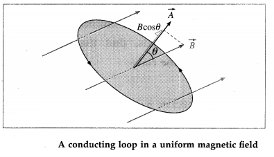
Since $\vec{B}$ is the same everywhere over $A$, the flux through the area $A$ is
$
\Phi_m=B A \cos \theta
$
where $\theta$ is the angle between $\vec{B}$ and $\vec{A}$.
Faraday's discovery was that the rate of change of flux $d \Phi_{ m } / dt$ is related to the work done on taking a unit positive charge around the contour in the reverse direction. This work done is just the induced emf. Accordingly we express Faraday's second law of electromagnetic induction as
$
| e |=\frac{d I _{ m }}{d t}=\frac{d}{d t}( BA \cos \theta)
$
If $B, A$ and $\theta$ are all constants in time, no emf is induced in the loop. An emf will be induced if at least one of these parameters changes with time. B and A may change in magnitude; the loop may turn, thereby changing $\theta$. View full question & answer→Question 444 Marks
How do you find the magnetic flux through a finite area A ?
AnswerConsider a small area element $\overrightarrow{d A}$ of a finite area $A$ bounded by contour $C$, from below figure. Suppose this area is situated in a magnetic field $\vec{B}$.
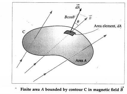
In general, the magnetic field may not be uniform over the area $A$. Then, the magnetic flux through the area element is $d \Phi_{ m }=\vec{B} \cdot \overrightarrow{d A}= B ( dA ) \cos \theta$
where $\theta$ is the angle between $\vec{B}$ and $\overrightarrow{d A}$, so that the flux through the area $A$ is
$
\Phi_{ m }=\int d \Phi_{ m }=\int_A \vec{B} \cdot \overrightarrow{d A}=\int_A B ( dA ) \cos \theta
$
The integration is over the entire area A. $\vec{B}$ can be taken out of the integral if and. only if $\vec{B}$ is the same everywhere over $A_{\text {, }}$ in which case,
$
\Phi_{ m }=\int_A B ( dA ) \cos \theta= B \cos \theta \int_A dA = BA \cos \theta
$
where $\int_A dA$ is just the total area $A$.
In general, the magnetic field may not be uniform over the area $A$. Then, the magnetic flux through the area element is $d \Phi_{ m }=\vec{B} \cdot \overrightarrow{d A}= B ( dA ) \cos \theta$
where $\theta$ is the angle between $\vec{B}$ and $\overrightarrow{d A}$, so that the flux through the area $A$ is
$
\Phi_{ m }=\int d \Phi_{ m }=\int_A \vec{B} \cdot \overrightarrow{d A}=\int_A B ( dA ) \cos \theta
$
The integration is over the entire area A. $\vec{B}$ can be taken out of the integral if and. only if $\vec{B}$ is the same everywhere over $A_{\text {, }}$ in which case,
$
\Phi_{ m }=\int_A B ( dA ) \cos \theta= B \cos \theta \int_A dA = BA \cos \theta
$
where $\int_A dA$ is just the total area $A$. View full question & answer→Question 454 Marks
Explain what you understand by magnetic flux.
AnswerThe total number of magnetic lines of force passing normally through a given area in a magnetic field, is called the magnetic flux through that area.
Consider a very small area dA in a uniform magnetic field of induction $\vec{B}$. The area dA can be represented by a vector $\overrightarrow{d A}$ perpendicular to it.
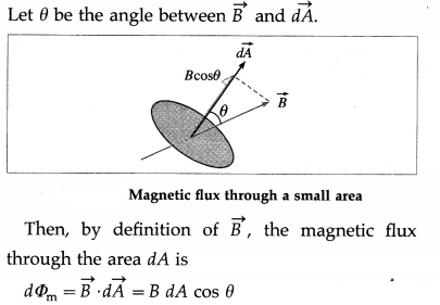
[Note : The area vector is perpendicular to the sur-face, so it can point either up and to the right as shown or down and to the left. Although either choice is acceptable, choosing the direction that is closest to the magnetic field is convenient and usually the one we choose.] View full question & answer→Question 464 Marks
Briefly explain the jumping ring experiment.
AnswerElihu Thompson’s jumping ring experiment is an outstanding demonstration of Faraday’s laws and Lenz’s law of electromagnetic induction. The apparatus consists of a cylindrical laminated iron- cored solenoid. A conducting non-magnetic ring, usually copper or aluminium, is placed over the extended vertical core of the solenoid. When an alternating current is passed through the solenoid, the ring is thrown off high into the air.

Due to ac, the magnetic field of the solenoid changes continuously. This induces eddy current in the ring. By Lenz’s law, the magnetic field produced by the induced eddy current in the ring opposes the changing magnetic field of the solenoid. Consequently, the two magnetic fields repel each other, making the ring jump.
The iron core increases the magnetic field of the solenoid. Often, the ring is cooled with liquid nitrogen. The colder the ring, the less is its resistance and greater the eddy current in it. More current means a greater magnetic field and even higher jumps.
View full question & answer→Question 474 Marks
State the causes of induced current and explain them on the basis of Lena's law.
Answer]
According to Lena's law, the direction of the induced emf or current is such as to oppose the change that produces it. The change that induces a current may be
(i) the motion of a conductor in a magnetic field or
(ii) the change of the magnetic flux through a stationary circuit.
In the first case, the direction of induced emf in the moving conductor Is such that the direction of the side-thrust exerted on the conductor by the magnetic field is opposite in direction to its motion. The motion of the conductor is, therefore, opposed.
In the second case, the induced current sets up a magnetic field of its own which within the area bounded by the circuit is (a) opposite to the original magnetic field if this field is increasing, but (b) is in the same direction as the original field, if the field is decreasing. Thus, it is the change in magnetic flux through the circuit (not the flux itself) which is opposed by the induced current.
View full question & answer→Question 484 Marks
Express Faraday-Lena's law of electromagnetic induction in an equation form.
AnswerSuppose $d \Phi_{ m }$ Is the change in the magnetic flux through a coil or circuit in time $dt$. Then, by Faraday's second law of electromagnetic induction, the magnitude of the einf Induced is $e \propto \frac{d \Phi_{ m }}{d t}$ or $e = k \frac{d T _{ m }}{d t}$
where $d \Phi_m / d t$ is the rate of change of magnetic flux
linked with the coil and k is a constant of proportionality. The Sl units of $e$ (the volt) and $d \Phi_m$ $df$ (the weber per second) are so selected that the constant of proportionality, $k$, becomes unity. Combining Faraday's law and Lents law of electromagnetic induction, the induced emf $e =-\frac{d \Phi_{ m }}{d t}$
where the minus sign is Included to indicate the polarity of the induced emf as given by Lents law. This polarity simply determines the direction of the induced current in a dosed loop. If a coil has $N$ tightly wound loops, the induced emf will be $N$ times greater than for a single loop, so that
$
e =- N \frac{d \Phi _{ m }}{d t}
$
where $\frac{d \Phi_m}{d t}$ is the rate of change of magnetic flux through one loop.
View full question & answer→Question 494 Marks
Describe Faraday’s coil-coil experiment. What conclusion can be drawn from the experiment?
Answer(1) A copper coil P of several turns is connected in series to a rheostat, a tap key and a battery. The terminals of another copper coil Q of several turns are connected to a sensitive galvanometer. The coils are placed close to each other such that when a current is passed through coil P by closing the key K, the magnetic flux through P is linked with coil Q.
(2) On closing the key K, the rise of current in coil P changes the flux linked with the coil Q nearby as shown by a momentary deflection (throw) of the galvanometer G, from below figure. A similar deflection in the same direction is seen if the key closed and either coil is moved swiftly towards the other.
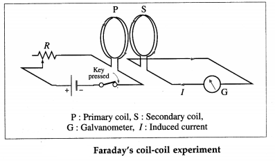
(3) On releasing the tap key, the current in the coil P does not reduce to zero instantaneously. With the decreasing flux through its turns, and a consequent decrease in the flux linked with coil Q, there is an opposite throw of the galvanometer. A similar deflection in the same direction is seen if the key is kept closed and either coil is moved swiftly away from the other.
Conclusion : A current is induced in an electric circuit whenever the magnetic flux linked with the circuit keeps on changing, either as a result of changing current in a nearby circuit or due to relative motion between them.
View full question & answer→Question 504 Marks
Describe Faraday’s magnet and coil experiment. What conclusion can be drawn from the experiment?
AnswerFaraday’s magnet and coil experiment:
1.The terminals of a copper coil of several turns are connected to a sensitive galvanometer.
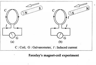
2.A bar magnet is moved swiftly towards the coil with its N-pole facing the coil. As long as the magnet is in motion, the galvanometer shows a deflection [from figure (a)].
3.If the magnet is now moved swiftly away from the coil, again the galvanometer shows a deflection, but now in the opposite direction.
4.The galvanometer shows a deflection when the experiment is repeated with the S-pole of the magnet facing the coil [from figure (b)]. However, the effect of bringing the S-pole towards the coil is the same as that of taking the N-pole away from the coil and vice versa.
5.The same results are obtained when the magnet is held still and the coil is moved towards or away from the magnet.
Conclusion : A current is induced in an electric circuit whenever the magnetic flux linked with the circuit keeps on changing as a result of relative motion of a magnet and the circuit.
View full question & answer→