$1.6\, mA$ current is flowing in conducting wire then the number of electrons flowing per second is
Easy
Download our app for free and get started
(b) $i = \frac{{ne}}{t}$==> $n = \frac{{it}}{e} = \frac{{1.6 \times {{10}^{ - 3}} \times 1}}{{1.6 \times {{10}^{ - 19}}}} = {10^{16}}$.

Download our appand get started for free
Experience the future of education. Simply download our apps or reach out to us for more information. Let's shape the future of learning together!No signup needed.*
Similar Questions
- 1Resistance of a wire at $0^{\circ} \mathrm{C}, 100^{\circ} \mathrm{C}$ and $t^{\circ} \mathrm{C}$ is found to be $10 \Omega, 10.2 \Omega$ and $10.95 \Omega$ respectively. The temperature $t$ in Kelvin scale is $\qquad$View Solution
- 2$A$ total charge $Q$ flows across a resistor $R$ during a time interval $= T$ in such a way that the current vs. time graph for $0 \rightarrow T$ is like the loop of a sin curve in the range $0 \rightarrow \pi$ . The total heat generated in the resistor isView Solution
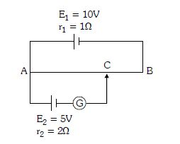
- 3In the figure the potentiometer wire of length $l =100\, cm$ and resistance $9\Omega$ is joined to a cell of emf $E_1 = 10V$ and internal resistance $r_1 = 1\Omega $. Another cell of emf $E_2 = 5\, V$ and internal resistance $r_2 = 2 \Omega $ is connected as shown. The galvanometer $G$ will show no deflection when the length $AC$ is ............... $cm$View Solution
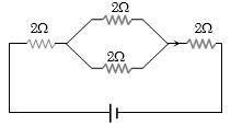
- 4The equivalent resistance of the circuit shown in the figure is ............. $\Omega$View Solution
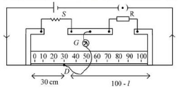
- 5In meter bridge experiment for measuring unknown resistance ' $S$ ', the null point is obtained at a distance $30 cm$ from the left side as shown at point $D$. If $R$ is $5.6 k \Omega$, then the value of unknown resistance ' $S$ ' will be $\Omega .$View Solution
- 6In a potentiometer arrangement, a cell of $emf$ $1.25\; V$ gives a balance point at $35.0\; cm$ length of the wire. If the cell is replaced by another cell and the balance point shifts to $63.0\; cm ,$ what is the $emf$ of the second cell in $V$?View Solution
- 7$STATEMENT-1$ In a Meter Bridge experiment, null point for an unknown resistance is measured. Now, the unknown resistance is put inside an enclosure maintained at a higher temperature. The null point can be obtained at the same point as before by decreasing the value of the standard resistance. andView Solution
$STATEMENT-2$ Resistance of a metal increases with increase in temperature.
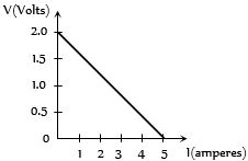
- 8For a cell, the graph between the potential difference $(V) $ across the terminals of the cell and the current $(I)$ drawn from the cell is shown in the figure. The $e.m.f.$ and the internal resistance of the cell areView Solution
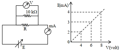
- 9To determine the resistance ($R$) of a wire, a circuit is designed below, The $V-I$ characteristic curve for this circuit is plotted for the voltmeter and the ammeter readings as shown in figure. The value of $\mathrm{R}$ is . . . . . . .$\Omega$View Solution
- 10View SolutionA steady current flows in a metallic conductor of non-uniform cross-section. The quantity/quantities constant along the length of the conductor is/are