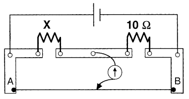
A meter bridge is set-up as shown, to determine an unknown resistance ' $X$ ' using a standard $10$ ohm resistor. The galvanometer shows null point when tapping-key is at $52 \ cm$ mark. The end-corrections are $1 \ cm$ and $2 \ cm$ respectively for the ends $A$ and $B$. The determined value of ' $X$ ' is
IIT 2011, Diffcult
Download our app for free and get started
Using the condition for balanced Wheatstone bridge, we get
$\frac{X}{10}=\frac{(52+1) cm }{(100-52+2) cm }=\frac{53}{50}$
or $X=\frac{53 \times 10}{50}=10.6 \ \Omega$

Download our appand get started for free
Experience the future of education. Simply download our apps or reach out to us for more information. Let's shape the future of learning together!No signup needed.*
Similar Questions
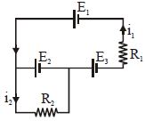
- 1The current $i_1$ and $i_2$ through the resistor $R_1 (= 10\,\Omega )$ and $R_2 (=30 \,\Omega )$ in the circuit diagram with $E_1 = 3\,V, E_2 = 3\,V$ and $E_3 = 2\,V$ are respectively:View Solution
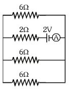
- 2The ammeter reading in the following circuit will be .............. $A$View Solution
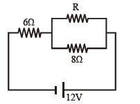
- 3In the circuit shown in figure, the power which is dissipated as heat in the $6\,\Omega$ resistor is $6\,W$. What is the value of resistance $R$ in the circuit?................... $\Omega$View Solution
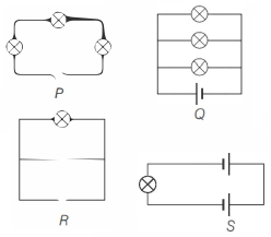
- 4Following figures show different combinations of identical bulb$(s)$ connected to identical battery$(ies)$. Which option is correct regarding the total power dissipated in the circuit?View Solution
- 5There are two electric bulbs of $40\, W$ and $100\, W$. Which one will be brighter when first connected in series and then in parallel,View Solution
- 6A carbon resistor of $(47 \pm 4.7) \;k\Omega$ is to be marked with rings of different colours for its identification. The colour code sequence will bView Solution
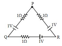
- 7In given circuit find potential difference between $P$ and $Q$ .................. $V$View Solution
- 8View SolutionA thick wire is stretched so that its length become two times. Assuming that there is no change in its density, then what is the ratio of change in resistance of wire to the initial resistance of wire
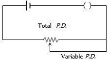
- 9View SolutionThe arrangement as shown in figure is called as
- 10A potential $V_0$ is applied across a uniform wire of resistance $R$. The power dissipation is $P_1$. The wire is then cut into two equal halves and a potential of $V _0$ is applied across the length of each half. The total power dissipation across two wires is $P_2$. The ratio $P_2: P_1$ is $\sqrt{x}: 1$. The value of $x$ is $.............$.View Solution