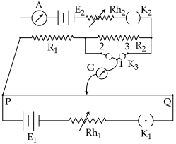
A potentiometer $PQ$ is set up to compare two resistances as shown in the figure. The ameter $A$ in the circuit reads $1.0\, A$ when two way key $K_3$ is open. The balance point is at a length $l_1\, cm$ from $P$ when two way key $K_3$ is plugged in between $2$ and $1$ , while the balance point is at a length $l_2\, cm$ from $P$ when key $K_3$ is plugged in between $3$ and $1$ . The ratio of two resistances $\frac{{{R_1}}}{{{R_2}}}$ is found to be
JEE MAIN 2017, Medium


Download our appand get started for free
Experience the future of education. Simply download our apps or reach out to us for more information. Let's shape the future of learning together!No signup needed.*
Similar Questions
- 1View SolutionAssertion : A current continues to flow in superconducting coil even after switch is off.
Reason : Superconducting coils show Meissner effect
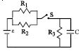
- 2The circuit shown in the figure consists of a battery of $emf$ $\varepsilon = 10 \,V$ ; a capacitor of capacitance $C = 1.0$ $ \mu F$ and three resistor of values $R_1 = 2$ $\Omega$ , $R_2 = 2$ $\Omega$ and $R_3 = 1$ $\Omega$ . Initially the capacitor is completely uncharged and the switch $S$ is open. The switch $S$ is closed at $t = 0.$View Solution
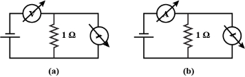
- 3A student uses the resistance of a known resistor $(1 \,\Omega)$ to calibrate a voltmeter and an ammeter using the circuits shown below. The student measures the ratio of the voltage to current to be $1 \times 10^3 \,\Omega$ in circuit $(a)$ and $0.999 \,\Omega$ in circuit $(b)$. From these measurements, the resistance (in $\Omega$ ) of the voltmeter and ammeter are found to be close toView Solution
- 4A house is served by $220\, V$ supply line in a circuit protected by a $9\, ampere$ fuse. The maximum number of $60\, W$ lamps in parallel that can be turned on, isView Solution
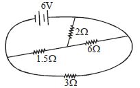
- 5Find the value of current from battery in the circuit ............... $A$View Solution
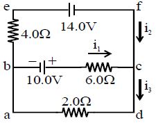
- 6Find the value of current $i_1$ for the circuit shown in figure :- ............ $A$View Solution
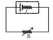
- 7Which of the following graphs represent the variation of power loss in the external load with external resistance $R$?View Solution
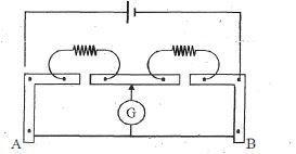
- 8A meter bridge set up as shown to determine end correction at $A$ and $B$ . When a resistance of $15\,\Omega $ is used in left gap and of $20\,\Omega $ in right gap, then null point comes at a distance $42\ cm$ from $A$ . When these resistances are interchanged null point comes at a distance $57\ cm$ from $A$ . Values of end corrections areView Solution
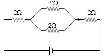
- 9The equivalent resistance of the circuit shown in the figure is ............. $\Omega$View Solution
- 10View SolutionWhen a piece of aluminium wire of finite length is drawn through a series of dies to reduce its diameter to half its original value, its resistance will become ........ times