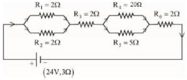
As shown in the figure, a network of resistors is connected to a battery of $2\,V$ with an internal resistance of $3\,\Omega$. The currents through the resistors $R_4$ and $R_5$ are $I_4$ and $I_5$ respectively. The values of $I_4$ and $I_5$ are :
JEE MAIN 2023, Diffcult


Download our appand get started for free
Experience the future of education. Simply download our apps or reach out to us for more information. Let's shape the future of learning together!No signup needed.*
Similar Questions
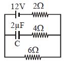
- 1Find the charge on the capacitor $C$ in the following circuit ............ $\mu C$View Solution
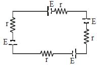
- 2Four identical cells of $EMF$ $E$ and internal resistance $r$ are connected as shown in figure, find terminal voltage across any one cellView Solution
- 3A $60\, watt$ bulb carries a current of $0.5\, amp$. The total charge passing through it in $1$ hour is ............ $coulomb$View Solution
- 4When a current of $2\,A$ flows in a battery from negative to positive terminal, the potential difference across it is $12\,V$. If a current of $3\,A$ flows in the opposite direction potential difference across the terminals of the battery is $15\,V$, the emf of the battery is ............... $\mathrm{V}$View Solution
- 5In a neon discharge tube $2.9 \times {10^{18}}\,N{e^ + }$ ions move to the right each second while $1.2 \times {10^{18}}$ electrons move to the left per second. Electron charge is $1.6 \times {10^{ - 19}}\,C$. The current in the discharge tubeView Solution
- 6A cell of constant $e.m.f.$ first connected to a resistance ${R_1}$ and then connected to a resistance ${R_2}$. If power delivered in both cases is then the internal resistance of the cell isView Solution
- 7A student is provided with a variable voltage source $V$, a test resistor $R_T=10\,\Omega$, two identical galvanometers $G_1$ and $G_2$ and two additional resistors, $R _1=10\,M\,\Omega$ and $R _2=0.001\,\Omega$. For conducting an experiment to verify ohms law, the most suitable circuit is:View Solution
- 8Consider four conducting materials copper, tungsten, mercury and aluminium with resistivity $\rho_{ C }, \rho_{ T }, \rho_{ M }$ and $\rho_{ A }$ espectively Then:View Solution
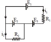
- 9The current $i_1$ and $i_2$ through the resistor $R_1 (= 10\,\Omega )$ and $R_2 (=30 \,\Omega )$ in the circuit diagram with $E_1 = 3\,V, E_2 = 3\,V$ and $E_3 = 2\,V$ are respectively:View Solution
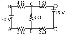
- 10The figure shows a network of five resistances and two batteries The current through the $30\,V$ battery is ............... $A$View Solution