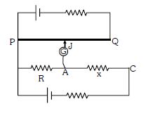
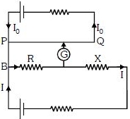
Circuit for the measurement of resistance by potentiometer is shown. The galvanometer is first connected at point $A$ and zero deflection is observed at length $P J = 10\ cm$ . In second case it is connected at point $C$ and zero deflection is observed at a length $30\ cm$ from $P$ . Then the unknown resistance $X$ is
Medium


Download our appand get started for free
Experience the future of education. Simply download our apps or reach out to us for more information. Let's shape the future of learning together!No signup needed.*
Similar Questions
- 1The charge flowing in a conductor changes with time as $Q ( t )=\alpha t -\beta t ^2+\gamma t ^3$. Where $\alpha, \beta$ and $\gamma$ are constants. Minimum value of current is :View Solution
- 2A constant electric current $I$ is passed through a straight conductor of length $l$. If $S$ in specific charge of electron then the total momentum of electrons isView Solution
- 3A resistance of $2\,\Omega $ is connected across one gap of a meter-bridge and unknown resistance, greater than $2\,\Omega $ , is connected a cross the other gap. When these resistances are interchanged, the balance point shifts by $20\ cm$ , neglecting any end correction, the unknown resistance is ................ $\Omega$View Solution
- 4Water boils in an electric kettle in $15\,\min$ after switching on. If the length of the heating wire is decreased to $2/3$ of its initial value, then the same amount of water will boil with the same supply voltage in ............. $min$View Solution
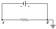
- 5A battery is connected to a uniform resistance wire $AB$ and $B$ is earthed. Which one of the graphs below shows how the current density $J$ varies along $AB$View Solution
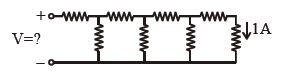
- 6Each element in the finite chain of resistors shown in the figure is $\,1\,\Omega $ . A current of $1\, A$ flows through the final element. Then what is the potential difference $V$ across input terminals of the chain .................. $\mathrm{volt}$View Solution
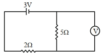
- 7As shown in the figure, the voltmeter reads $2\,V$ across $5\,\Omega$ resistor. The resistance of the voltmeter is $.......\,\Omega$.View Solution
- 8If a $0.1\%$ increase in length due to stretching, the percentage increase in its resistance will be ............ $\%$View Solution
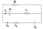
- 9View SolutionSee the electrical circuit shown in this figure. Which of the following equations is a correct equation for it ?
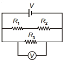
- 10In the circuit shown, $R_1$ is increased. What happens to the reading of the voltmeter (ideal)?View Solution