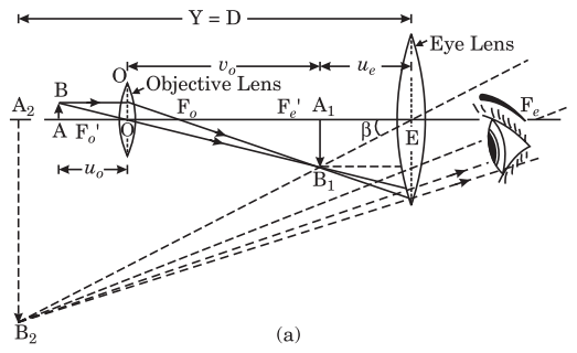
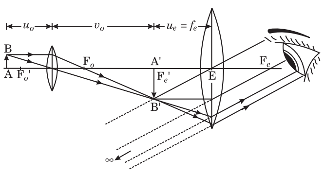
Question
Explain with a neat diagram construction and working of a compound microscope. Obtain an expression for its magnifying power.

Answer

Compound Microscope : In order to obtain higher magnifying power compound microscope is used.
Construction : It consists of two converging lenses. The lenses themselves are a suitable combination of lenses which avoids the various aberrations. The lens which is towards the object is called objective lens and the lens which is towards the eye is called eye piece. The objective lens has a wide aperture so as to cover up a wide field of vision and the eye-piece is of small aperture. In this microscope two convex lenses are used and magnification takes place in two steps hence it is called compound microscope.
Image
Both the lenses are fitted in brass tubes, one of the tubes can slide into the other. This distance of eye-piece from the objective can be changed by moving the tube containing eyepiece by rack and pinion arrangement. The tube containing the eye-piece is fitted with cross wires to make measurements. These are two fine wires at right angles to each other. The distance between the objective and eye-piece is so adjusted that the image formed by the objective falls on cross wires. The compound microscope used in Biology has different eye-pieces of different power and a plane mirror is used to illuminate the object by reflection.
Formation of Image : The image formation by compound microscope is shown in Fig. (a) given above. In this figure let AB be an object to be seen. It is placed infront of the objective at a distance slightly greater than the focal length of the objective lens. By the objective lens a real, inverted and magnified image A1B1 is formed. The distance of eye lens is so adjusted that image A1B1 lies within the focal length of the eye lens. The image A1B1 acts as an object for eye lens and magnified virtual image A2B2 is formed by the eye-piece. Thus, the final image A2B2 is seen through the eye-piece which is formed at the least distance of distinct vision.
If the image A1B1 is formed at the focus Fe of the eye-piece then the final image will be form at infinity.
Magnifying power : Magnifying power of a microscope is given by :
$M =\frac{\begin{array}{c}\text { Anglesubtended bythe } \\ \text { finalimageattheeye }\end{array}}{\begin{array}{c}\text { Anglesubtendedby theobject } \\ \text { placed attheleastdistance of distinct } \\ \text { visionandisbeing vieweddirectly }\end{array}}$
Let final image A2B2 subtend an angle $\beta$ at the eye lens E. Since eye is very near to eye lens, hence this angle $\beta$ can also be taken as subtended at the eye. Let the angle subtended at eye be a when the object AB is at least distance of distinct vision D.
Thus $M=\frac{\beta}{\alpha}=\frac{\tan \beta}{\tan \alpha}$
(since angle $\beta$ and $\alpha$ are very small)
$=\frac{A_1 B_1 / E A_1}{A B / D}=\left(\frac{A_1 B_1}{A B}\right) \times\left(\frac{D}{E A_1}\right)$
If u0 and v0 be the distances of object and image from objective lens, then from magnification formula of lens (taking proper sign) $\frac{ A _1 B_1}{ AB }=\frac{+v_o}{-u_o}$. If ue be the distance of A1B1 from eye lens then EA1 = - ue. Hence
Image
$M =-\frac{v_o}{u_o}\left(\frac{- D }{-u_e}\right)$
$\Rightarrow \quad M =-\frac{v_o}{u_o}\left(\frac{ D }{u_e}\right)$ ...(1)
If final image A₂B₂ is formed at $v_e$ from the eye lens then for this lens :
$v=v_e ; u=-u_e$ and $f=+f_e$
where $f_e$ = focal length of the eye lens. Then lens formula :
$\frac{1}{v}-\frac{1}{u}=\frac{1}{f} \Rightarrow \frac{1}{-v_e}-\frac{1}{-u_e}=\frac{1}{f_e}$
$\Rightarrow \quad \frac{1}{u_e}=\frac{1}{v_e}+\frac{1}{f_e}=\frac{1}{v_e}\left(1+\frac{v_e}{f_e}\right)$
Now substituting this value of $1 / u _e$ in above equation (1), we get
$M =-\left(\frac{v_o}{u_o}\right) \times D \left[\frac{1}{v_e}\left(1+\frac{v_e}{f_e}\right)\right]$
$\Rightarrow \quad M =-\left(\frac{ v _o}{ u _o}\right)\left(\frac{ D }{ v _{ e }}\right)\left( 1 +\frac{ v _{ e }}{ f _{ e }}\right)$ ...(2)
Now the following two cases are possible :
(i) If final image A2B2 is formed at least distance of distinct vision D then ve = D and from equation (2),
$M =-\left[\frac{ v _o}{u_o}\left( 1 +\frac{ D }{f_e}\right)\right]$ ...(3)
(ii) For relaxed eye final image A2B2 is formed at infinity In this case image A1B1 will be at the focus of eye lens $E \Rightarrow u _e= f _e$. Substituting this value of ue in equation (1), we get
$M =-\left[\frac{ v _o}{u_o}\left(\frac{ D }{ f _e}\right)\right]$ ...(4)
Image formation ray diagram in this case is shown in fig. (c).
The negative sign in the formulae (3) and (4) for magnifying power in both the cases represents that final image formed in both the cases is inverted with respect to the object.
Image

Need a full question paper?

Generate a complete, print-ready paper with questions like this in minutes — across 16+ boards, with answer keys.

Start Generating Free

Similar questions

A source of sound operates at $2.0kHz, 20W$ emitting sound uniformly in all directions. The speed of sound in air is $340\ m/s$ and the density of air is $1.2\ kg/m^3.$
  1. What is the intensity at a distance of 6.0m from the source?
  2. What will be the pressure amplitude at this point?
  3. What will be the displacement amplitude at this point ?
Establish an expression for induced electromotive force due to rotational motion of a conducting rod in a uniform magnetic field.
Two fixed, identical conducting plates $(\alpha\ \&\ \beta)$, each of surface area S are charged to -Q and q, respectively, where Q > q > 0. A third identical plate $(\gamma)$, free to move is located on the other side of the plate with charge q at a distance d (Fig.). The third plate is released and collides with the plate $\beta$. Assume the collision is elastic and the time of collision is sufficient to redistribute charge amongst $\beta\ \&\ \gamma$.

Find the electric field acting on the plate $\gamma$ before collision.
Two conducting plates X and Y, each having large surface area A (on one side), are placed parallel to each other as shown in figure. The plate X is given a charge Q whereas the other is neutral. Find:
  1. The surface charge density at the inner surface of the plate X.
  2. The electric field at a point to the left of the plates.
  3. The electric field at a point in between the plates.
  4. The electric field at a point to the right of the plates.
$a$. Draw graphs showing the variations of inductive reactance and capacitive reactance with the frequency of the applied ac source.
$b$. Draw the phasor diagram for a series $RC$ circuit connected to an ac source.
$c$. An alternating voltage of $220 V$ is applied across a device $X,$ a current of $0.25$ A flows, which lag behind the applied voltage in phase by $\frac{\pi}{2}$ radian. If the same voltage is applied across another device $Y,$ the same current flows but now it is in phase with the applied voltage.
$i$. Name the devices $X$ and $Y$.
$ii$. Calculate the current flowing in the circuit when the same voltage is applied across the series combination of $X$ and $Y$.
Consider the de Broglie wavelength of an electron and a proton. Which wavelength is smaller if the two particles have.
  1. The same speed.
  2. The same momentum.
  3. The same energy?.
Solve the previous problem if the friction coefficient between the $2.0\ kg$ block and the plane below it is $0.5$ and the plane below the $4.0\ kg$ block is frictionless.
Explain construction and working of a nuclear reactor. State its utility also.
A smooth wedge A is fitted in a chamber hanging from a fixed ceiling near the earth's surface. A block B placed at the top of the wedge takes a time T to slide down the length of the wedge. If the block is placed at the top of the wedge and the cable supporting the chamber is broken at the same instant, the block will:
  1. Take a time longer than T to slide down the wedge.
  2. Take a time shorter than T to slide down the wedge.
  3. Remain at the top of the wedge.
  4. Jump off the wedge.
A magnetic field in a certain region is given by $\text{B}=\text{B}_0\cos(\omega\text{t})\hat{\text{k}}$ and a coil of radius a with resistance R is placed in the x-y plane with its centre at the origin in the magnetic field (see Fig). Find the magnitude and the direction of the current at (a, 0, 0) at $\text{t}=\frac{\pi}{2\omega},\text{t}=\frac{\pi}{\omega} \text{ and }\text{t}=\frac{3\pi}{2\omega}$.