MCQ
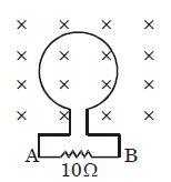
Figure shows a conducting loop placed in magnetic field. The flux through the loop changes due to change in magnetic field according to the equation $\phi  = 5t - 10{t^2}$. What is direction and magnitude of induced current at $t = 0.25\, s$ ?
  • A
    $0.5\,A,\, A\to B$
  • B
    $0.5\,A,\, B\to A$
  • C
    $1.5\,A,\, A\to B$
  • Zero

Answer

Correct option: D.
Zero
d
$\mathrm{Emf}=\frac{-\mathrm{d} \phi}{\mathrm{dt}}=-[5-20 \mathrm{t}]=-\left[5-20 \times \frac{1}{4}\right]=0$

Induced current $=0$

Need a full question paper?

Generate a complete, print-ready paper with questions like this in minutes — across 16+ boards, with answer keys.

Start Generating Free

Similar questions

A sphere is rotating about a diameter:
Two long parallel wires carrying currents $8\,A$ and $15\,A$ in opposite directions are placed at a distance of $7\,cm$ from each other. A point $P$ is at equidistant from both the wires such that the lines joining the point $P$ to the wires are perpendicular to each other. The magnitude of magnetic field at $P$ is $............\times 10^{-6}\,T$. (Given : $\left.\sqrt{2}=1.4\right)$
Control rods used in nuclear reactors are made of:
Which is the factor that internal resistance does not depend on?
Pick out the correct increasing order of energy of electromagnetic waves from the following:
$A$ student is asked to measure the wavelength of monochromatic light. He sets up the apparatus sketched below. $S_1, S_2, S_3$ are narrow parallel slits, $L$ is a sodium lamp and $M$ is a microscope eyepiece. The student fails to observe interference fringes. Your first advice to him will be
In the given $A.C.$ circuit, the instantaneous current through inductor and capacitor are $0.8 \,A$ and $0.4 \,A$ respectively. The instantaneous current through resistor is ........ 
Product of resistivity and conductivity of any conductor depends on:
The figure shown has two coils of wires placed in close proximity. The current in primary coil $P$ is made to vary with time as shown in the graph, which of the following graphs best represents the variation of the emf induced in the secondary coil $S$ ?
A rectangular conducting loop of length $4 \mathrm{~cm}$ and width $2 \mathrm{~cm}$ is in the $x y$-plane, as shown in the figure. It is being moved away from a thin and long conducting wire along the direction $\frac{\sqrt{3}}{2} \hat{x}+\frac{1}{2} \hat{y}$ with a constant speed $v$. The wire is carrying a steady current $\mathrm{I}=10 \mathrm{~A}$ in the positive $x$-direction. A current of $10 \mu \mathrm{A}$ flows through the loop when it is at a distance $d=4 \mathrm{~cm}$ from the wire. If the resistance of the loop is $0.1 \Omega$, then the value of $v$ is. . . . . . .$\mathrm{ms}^{-1}$.

[Given: The permeability of free space $\mu_0=4 \pi \times 10^{-7} \mathrm{NA}^{-2}$ ]