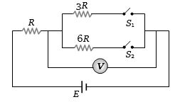
In the circuit shown in figure reading of voltmeter is $V_1$ when only $S_1$ is closed, reading of voltmeter is $ V_2$ when only $S_2$ is closed and reading of voltmeter is $V_3$ when both $S_1$ and $S_2$ are closed. Then
Medium


Download our appand get started for free
Experience the future of education. Simply download our apps or reach out to us for more information. Let's shape the future of learning together!No signup needed.*
Similar Questions
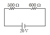
- 1Two resistors are connected in series across a battery as shown in figure. If a voltmeter of resistance $2000 \,\Omega$ is used to measure the potential difference across $500 \,\Omega$ resister, the reading of the voltmeter will be ............... $V$View Solution
- 2A wire of $1 \,\Omega$ has a length of $1\, m$. It is stetched till its length increases by $25\, \%$. The percentage change in resistance to the neartest integer is .....$\%$View Solution
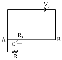
- 3The sliding contact $C$ is at one fourth of the length of the potentiometer wire $( AB )$ from $A$ as shown in the circuit diagram. If the resistance of the wire $AB$ is $R _0$, then the potential drop $( V )$ across the resistor $R$ isView Solution
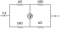
- 4In the circuit shown below, The reading of the voltmeter $V$ is ...........View Solution
- 5Ratio of thermal energy released in two resistor $R$ and $3 R$ connected in parallel in an electric circuit is :View Solution
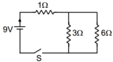
- 6After switch is closed, current drawn from the battery is (in $A$)View Solution
- 7A $3\,^oC$ rise in temperature is observed in a conductor by passing a certain current. When the current is doubled, the rise in temperature will be ............. $^oC$View Solution
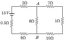
- 8The current from the battery in circuit diagram shown is .............. $A$View Solution
- 9Copper and silicon is cooled from $300\; K$ to $60\; K$, the specific resistanceView Solution
- 10$A$ total charge $Q$ flows across a resistor $R$ during a time interval $= T$ in such a way that the current vs. time graph for $0 \rightarrow T$ is like the loop of a sin curve in the range $0 \rightarrow \pi$ . The total heat generated in the resistor isView Solution