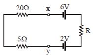
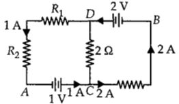
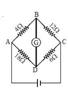
In the circuit shown in the figure, if the potential at point $A$ is taken to be zero, the potential at point $B$ is ................ $V$
AIPMT 2011, Medium
Download our app for free and get started
Applying Kirchoff voltage law in the circuit as shown in the figure below.
$\therefore V_{A}+1+2(1)-2=V_{B} $
$0+1 =V_{B} \left(\because V_{A}=0 \mathrm{V}(\text { Given })\right) $
$V_{B} =+1 \mathrm{V}$

Download our appand get started for free
Experience the future of education. Simply download our apps or reach out to us for more information. Let's shape the future of learning together!No signup needed.*
Similar Questions
- 1The resistance per centimeter of a meter bridge wire is $\mathrm{r}$, with $\mathrm{X}\ \Omega$ resistance in left gap. Balancing length from left end is at $40 \mathrm{~cm}$ with $25\ \Omega$ resistance in right gap. Now the wire is replaced by another wire of $2 \mathrm{r}$ resistance per centimeter. The new balancing length for same settings will be atView Solution
- 2Heat produced in a wire of resistance $R$ due to current flowing at constant potential difference is proportional toView Solution
- 3A potentiometer consists of two wires $AC$ and $CB$ of same material and of equal lengths but diameters in the ratio $3 : 1.$ Then the potential gradients on the two wires will be in the ratio :-View Solution
- 4A student is provided with a variable voltage source $V$, a test resistor $R_T=10\,\Omega$, two identical galvanometers $G_1$ and $G_2$ and two additional resistors, $R _1=10\,M\,\Omega$ and $R _2=0.001\,\Omega$. For conducting an experiment to verify ohms law, the most suitable circuit is:View Solution
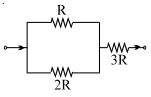
- 5The ratio of powers dissipatted respectively in $R$ and $3R$, as shown is:View Solution
- 6View SolutionIn the following diagram the wheat stone bridge is balanced when we interchange the resistances of
- 7A potentiometer wire, $10\,m$ long, has a resistance of $40\,\Omega $. It is connected in series with a resistance box and a $2\,V$ storage cell. If the potential gradient along the wire is $0.1\,m\,V/cm$, the resistance unplugged in the box is .............. $\Omega$View Solution
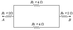
- 8In the given figure, the equivalent resistance between the points $A$ and $B$ is ............ $\Omega$View Solution
- 9View SolutionAssertion : Kirchoff 's junction rule follows from conservation of charge.
Reason : Kirchoff 's loop rule follows from conservation of momentum.
- 10The current flowing in the given circuit is $0.1\,A$ . The potential difference between the points $X$ and $Y$ is ................ $\mathrm{V}$View Solution