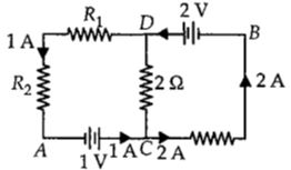
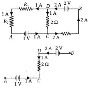
In the circuit shown in the figure, if the potential at point $A$ is taken to be zero, the potential at point $B$ is ................ $V$
AIPMT 2011, Medium


Download our appand get started for free
Experience the future of education. Simply download our apps or reach out to us for more information. Let's shape the future of learning together!No signup needed.*
Similar Questions
- 1Which of the following graphs represent the variation of power loss in the external load with external resistance $R$?View Solution
- 2The equivalent resistance betweent point $A$ and $B$View Solution
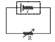
- 3A battery of $e.m.f.$ $10\, V$ and internal resistance $0.5\, ohm$ is connected across a variable resistance $R$. The value of $R$ for which the power delivered in it is maximum is given by ......... $ohm$View Solution
- 4A copper rod of cross-sectional area $A$ carries a uniform current $I$ through it. At temperature $T$, if the volume charge density of the rod is $\rho $, how long will the charges take to travel a distance $d$ ?View Solution
- 5An ideal battery of $4\, V$ and resistance $R$ are connected in series in the primary circuit of a potentiometer of length $1\, m$ and resistance $5\,\Omega $ . The value of $R$, to give a difference of $5\, mV$ across $10\, cm$ of potentiometer wire, is: ................ $\Omega$View Solution
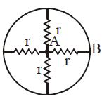
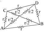
- 6The figure shows a tetrahedron, each side of which has a resistance $r$ If a battery is connected between any two points of the tetrahedron, then identify the correct statement $(s)$.View Solution
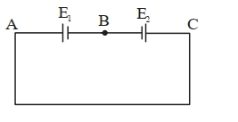
- 7Two cells are connected in opposition as shown. Cell $\mathrm{E}_1$ is of $8 \mathrm{~V}$ emf and $2 \ \Omega$ internal resistance; the cell $E_2$ is of $2 \mathrm{~V}$ emf and $4\ \Omega$ internal resistance. The terminal potential difference of cell $\mathrm{E}_2$ is:View Solution
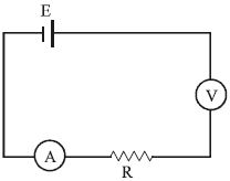
- 8Assertion : All electric devices shown in the circuit are ideal. The reading of each of ammeter $(a)$ and voltmeter $(V)$ is zero.View Solution
Reason : An ideal voltmeter draws almost no current due to very large resistance, and hence $(V)$ and $(a)$ will read zero.
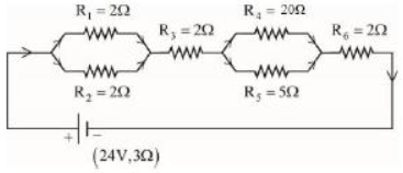
- 9As shown in the figure, a network of resistors is connected to a battery of $2\,V$ with an internal resistance of $3\,\Omega$. The currents through the resistors $R_4$ and $R_5$ are $I_4$ and $I_5$ respectively. The values of $I_4$ and $I_5$ are :View Solution
- 10This question contains statement$-1$ and statement$-2$. Of the four choices given after the statements, choose the one that best describes the two statements.View Solution
statement$-1$ : The temperature dependence of resistance is usually given as $R=R_{0}(1+\alpha \Delta t)$. The resistance of a wire changes from $100\; \Omega$ to $150\; \Omega$ when its temperature is increased from $27^{\circ} C$ to $227^{\circ} C$. This implies that $\alpha=2.5$ $\times 10^{-3} /{ }^{\circ} C$
statement$-2\;: R=R_{0}(1+\alpha \Delta t)$ is valid only when the change in the temperature $\Delta T$ is small and $\Delta R=\left(R-R_{0}\right) < < R_{0}$