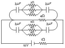
In the following figure, the charge on each condenser in the steady state will be.....$\mu C$
Medium
Download our app for free and get started
(d) In steady state current flows through $4\, \Omega$ resistance only and it is $i = \frac{{10}}{{(4 + 1)}} = 2\,amp$.
Potential difference across $4\, \Omega$ resistance is $V = 2 \times 4 = 8\,volt$
Hence, potential difference across each capacitor is $4\,V$
So charge on each capacitor $Q = 3 \times 4 = 12 \,\mu C$.

Download our appand get started for free
Experience the future of education. Simply download our apps or reach out to us for more information. Let's shape the future of learning together!No signup needed.*
Similar Questions
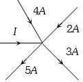
- 1In the given current distribution what is the value of $I$ .............. $A$View Solution
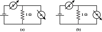
- 2A student uses the resistance of a known resistor $(1 \,\Omega)$ to calibrate a voltmeter and an ammeter using the circuits shown below. The student measures the ratio of the voltage to current to be $1 \times 10^3 \,\Omega$ in circuit $(a)$ and $0.999 \,\Omega$ in circuit $(b)$. From these measurements, the resistance (in $\Omega$ ) of the voltmeter and ammeter are found to be close toView Solution
- 3The length of a wire of a potentiometer is $100\, cm$, and the $emf$ of its standard cell is $E\,volt$. It is employed to measure the $e.m.f$ of a battery whose internal resistance is $0.5 \,\Omega$. If the balance point is obtained at $l = 30\, cm$ from the positive end, the $e.m.f.$ of the battery isView Solution
where $i$ is the current in the potentiometer
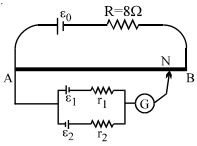
- 4$A$ battery of $\mathrm{emf}$ $E_0 = 12\, V$ is connected across a $4\,m$ long uniform wire having resistance $4\,\Omega /m$. The cells of small $\mathrm{emfs}$ $\varepsilon_1 = 2\,V$ and $\varepsilon_2 = 4\,V$ having internal resistance $2\Omega$ and $6\Omega$ respectively, are connected as shown in the figure. If galvanometer shows no deflection at the point $N$, the distance of point $N$ from the point $A$ is equal toView Solution
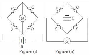
- 5Figure $(i)$ below shows a Wheatstone's bridge in which $P, Q, R$ and $S$ are fixed resistances, $G$ is a galvanometer and $B$ is a battery. For this particular case, the galvanometer shows zero deflection. Now, only the positions of $B$ and $G$ are interchanged, as shown in figure $(ii)$. The new deflection of the galvanometerView Solution
- 6A steady current $i$ is flowing through a conductor of uniform cross-section. Any segment of the conductor hasView Solution
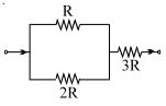
- 7The ratio of powers dissipatted respectively in $R$ and $3R$, as shown is:View Solution
- 8$1.6\, mA$ current is flowing in conducting wire then the number of electrons flowing per second isView Solution
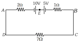
- 9View SolutionThe magnitude and direction of the current in the following circuit is :-
- 10View SolutionA steady current flows in a metallic conductor of non-uniform cross-section. The quantity/quantities constant along the length of the conductor is/are