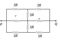
The effective resistance between points $P$ and $Q$ of the electrical circuit shown in the figure is
IIT 2002, Medium
Download our app for free and get started
In a circuit, any circuit element placed between points at the same potential can be removed, without affecting the rest of the circuit. Here, by symmetry, points $A$, $B$ and $C$ are at same potential, for any potential difference between $P$ and $Q$.
The circuit can therefore be reduced as shown below
Effective resistance ${R_{eq}} = \frac{{2Rr}}{{R + r}}$.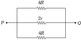

Download our appand get started for free
Experience the future of education. Simply download our apps or reach out to us for more information. Let's shape the future of learning together!No signup needed.*
Similar Questions
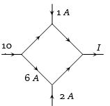
- 1The figure shows a network of currents. The magnitude of currents is shown here. The current $I$ will be ........... $A$View Solution
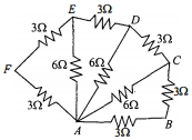
- 2Six resistors of $3 \;\Omega$ each are connected along the sides of a hexagon and three resistors of $6\; \Omega$ each are connected along $A C, A D$ and $A E$ as shown in the figure. The equivalent resistance between $A$ and $B$ is equal toView Solution
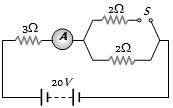
- 3In the circuit shown, the reading of ammeter when switch $S$ is open and when switch $S$ is closed respectively areView Solution
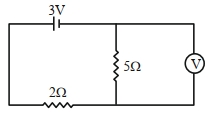
- 4As shown in the figure, the voltmeter reads $2\,V$ across $5\,\Omega$ resistor. The resistance of the voltmeter is $.......\,\Omega$.View Solution
- 5A $220\, volt$, $1000\, W$ bulb is connected across a $110\, volt$ mains supply. The power consumed will be ............ $W$View Solution
- 6A metal wire has a resistance of $35 \,\Omega$. If its length is increased to double by drawing it, then its new resistance will be (in $\Omega$)View Solution
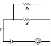
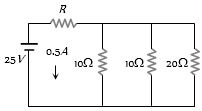
- 7If a resistance ${R_2}$ is connected in parallel with the resistance $R$ in the circuit shown, then possible value of current through $R$ and the possible value of ${R_2}$ will beView Solution
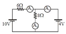
- 8Reading of ammeter $A_1, A_2$ and $A_3$ will be respectivelyView Solution
- 9View SolutionIn the circuit as shown in figure the
- 10As shown, the circuit is made of $8$ different resistors. It is found that when $R_1 = 4\,\,\Omega,$ the resistance between $A$ and $B$ is $2\,\,\Omega.$ Now replace $R_1$ by a $6\,\,\Omega$ resistor, what is the resistance between $A$ and $B$?View Solution