The e.m.f. of a cell is $E\, volts$ and internal resistance is $r$ $ohm$. The resistance in external circuit is also $r$ $ohm$. The p.d. across the cell will be
Easy
Download our app for free and get started
(a) Since both the resistors are same, therefore potential difference $ = V + V = E$ $ \Rightarrow $ $V = \frac{E}{2}$

Download our appand get started for free
Experience the future of education. Simply download our apps or reach out to us for more information. Let's shape the future of learning together!No signup needed.*
Similar Questions
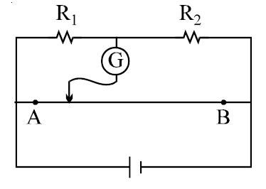
- 1In the figure shown for gives values of $R_1$ and $R_2$ the balance point for Jockey is at $40\,cm$ from $A$. When $R_2$ is shunted by a resistance of $10\, \Omega$ , balance shifts to $50\,cm.$ $R_1$ and $R_2$ are $(AB = 1 \,m)$View Solution
- 2Two electric bulbs whose resistances are in the ratio of $1 : 2$ are connected in series. The powers dissipated in them have the ratioView Solution
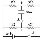
- 3In the circuit shown in figure, switch $S_1$ is initially closed and $S_2$ is open. Find $V_a -V_b$ .............. $V$View Solution
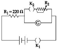
- 4The galvanometer deflection, when key $K_1$ is closed but $K_2$ is open, equals $\theta_0$ (see figure). On closing $K_2$ also and adjusting $R_2$ to $5\,\Omega $ , the deflection in galvanometer becomes $\frac{{\theta _0}}{5}$. The resistance of the galvanometer is, then, given by [Neglect the internal resistance of battery]: .................. $\Omega$View Solution
- 5View SolutionFor which of the following the resistance decreases on increasing the temperature
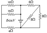
- 6Find the equivalent resistance across the terminals of source of $e.m.f$. $24\, V$ for the circuit shown in figure .............. $\Omega$View Solution
- 7$n$ identical cells are joined in series with its two cells $A$ and $B$ in the loop with reversed polarities. $EMF$ of each shell is $E$ and internal resistance $r$. Potential difference across cell $A$ or $B$ is (here $n > 4$)View Solution
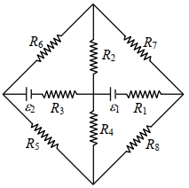
- 8The figure shows a circuit having eight resistances of $1 \Omega$ each, labelled $R_1$ to $R_8$, and two ideal batteries with voltages $\varepsilon_1=12 V$ and $\varepsilon_2=6 V$.View Solution
Which of the following statement($s$) is(are) correct?
$(A)$ The magnitude of current flowing through $R_1$ is $7.2 A$.
$(B)$ The magnitude of current flowing through $R_2$ is $1.2 A$.
$(C)$ The magnitude of current flowing through $R_3$ is $4.8 A$.
$(D)$ The magnitude of current flowing through $R_5$ is $2.4 A$.
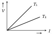
- 9The voltage $V$ and current $I$ graph for a conductor at two different temperatures ${T_1}$ and ${T_2}$ are shown in the figure. The relation between ${T_1}$ and ${T_2}$ isView Solution
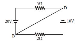
- 10Calculate the current in wire $BD$ ................ $A$View Solution