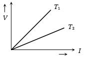
The voltage $V$ and current $I$ graph for a conductor at two different temperatures ${T_1}$ and ${T_2}$ are shown in the figure. The relation between ${T_1}$ and ${T_2}$ is
Easy
Download our app for free and get started
Slope of the $V-i$ curve at any point equal to resistance at that point. From the curve slope for $T_1$ > slope for $T_2$
$ \Rightarrow $ ${R_{{T_1}}} > {R_{{T_2}}}$. Also at higher temperature resistance will be higher so $T_1 > T_2$

Download our appand get started for free
Experience the future of education. Simply download our apps or reach out to us for more information. Let's shape the future of learning together!No signup needed.*
Similar Questions
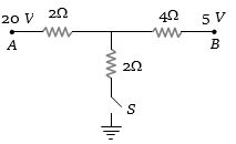
- 1As the switch $S$ is closed in the circuit shown in figure, current passed through it is .................. $A$View Solution
- 2Consider a block of conducting material ofresistivity '$\rho$' shown in the figure. Current '$I$' enters at '$A$' and leaves from '$D$'. We apply superp osition principle to find voltage '$\Delta V$ ' developed between '$B$' and '$C$'. The calculation is done in the following steps:View Solution
$(i)$ Take current '$I$' entering from '$A$' and assume it to spread over a hemispherical surface in the block.
$(ii)$ Calculatefield $E(r)$ at distance '$r$' from $A$ by using Ohm's law $E = \rho j$, where j is the current per unit area at '$r$'.
$(iii)$ From the '$r$' dependence of $E(r)$, obtain the potential $V(r)$ at $r$.
$(iv)$ Repeat $(i), (ii)$ and $(iii)$ for current '$I$' leaving '$D$' and superpose results for '$A$' and '$D$'.For current entering at $A$, the electric field at a distance '$r$'
from $A$ is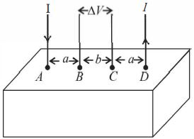
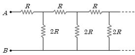
- 3An infinite ladder network is arranged with resistances $R$ and $2 R$ as shown. The effective resistance between terminals $A$ and $B$ isView Solution
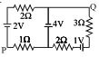
- 4In the circuit shown, what is the potential difference $V_{PQ}$? ................ $V$View Solution
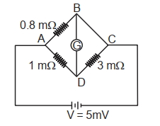
- 5To measure the temperature coefficient of resistivity $\alpha$ of a semiconductor, an electrical arrangement shown in the figure is prepared. The arm BC is made up of the semiconductor. The experiment is being conducted at $25^{\circ} \mathrm{C}$ and resistance of the semiconductor arm is $3 \mathrm{~m} \Omega$. Arm BC is cooled at a constant rate of $2^{\circ} \mathrm{C} / \mathrm{s}$. If the galvanometer $\mathrm{G}$ shows no deflection after $10 \mathrm{~s}$, then $\alpha$ is :View Solution
- 6The supply voltage to room is $120\ V$. The resistance of the lead wires is $6\,\Omega$ . A $60\ W$ bulb is already switched on. What is the decrease of voltage across the bulb, when a $240\ W$ heater is switched on in parallel to the bulb? ............. $V$View Solution
- 7Two identical heaters rated $220\, volt$, $1000\, watt$ are placed in series with each other across $220 \,volt$ lines. If resistance do not change with temperature, then the combined power is ............. $watt$View Solution
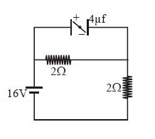
- 8What is net force on the small dipole placed inside the capacitor at steady state if the plates are separated by $1\ cm$ ?......$N$View Solution
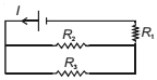
- 9Refer to the circuit shown. What will be the total power dissipation in the circuit if $P$ is the power dissipated in $R_1$ ? It is given that $R_2=4 R_1$ and $R_3=12 R_1$ are .......... $P$View Solution
- 10For comparing the $e.m.f.$'s of two cells with a potentiometer, a standard cell is used to develop a potential gradient along the wires. Which of the following possibilities would make the experiment unsuccessfulView Solution