The figure shows a circuit having eight resistances of $1 \Omega$ each, labelled $R_1$ to $R_8$, and two ideal batteries with voltages $\varepsilon_1=12 V$ and $\varepsilon_2=6 V$.
Which of the following statement($s$) is(are) correct?
$(A)$ The magnitude of current flowing through $R_1$ is $7.2 A$.
$(B)$ The magnitude of current flowing through $R_2$ is $1.2 A$.
$(C)$ The magnitude of current flowing through $R_3$ is $4.8 A$.
$(D)$ The magnitude of current flowing through $R_5$ is $2.4 A$.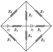
IIT 2022, Advanced
Download our app for free and get started
From $KCL$
$i _1+ i _2+ i _3=0$
$\Rightarrow \frac{18- V _0}{3 / 2}+\frac{12- V _0}{1 / 2}+\frac{0- V _0}{3 / 2}=0$
$\Rightarrow 18- V _0+36-3 V _0- V _0=0$
$\Rightarrow 54=5 V _0$
$\frac{2\left(\frac{54}{5}- v ^{\prime}\right)}{1}+\frac{18- v ^{\prime}}{1}=0 $
$\Rightarrow \frac{108}{5}+18=3 V ^{\prime}$
$\Rightarrow v ^{\prime}=\frac{198}{5 \times 3}=\frac{66}{5} V$
$I _{ R _1}=\frac{36}{5}=7.2 A$
$I _{ R _2}=\frac{6}{5}=1.2 A$
$I _{ R _3}=\frac{24}{5}=4.8 A$
$I _{ R _s}=\frac{12}{5}=2.4 A$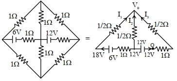

Download our appand get started for free
Experience the future of education. Simply download our apps or reach out to us for more information. Let's shape the future of learning together!No signup needed.*
Similar Questions
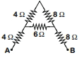
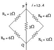
- 1The equivalent resistance between $A$ and $B$ for the mesh shown in the figure is ......... $\Omega$View Solution
- 2When a potential difference $V$ is applied across a wire of resistance $R$, it dissipates energy at a rate $W$. If the wire is cut into two halves and these halves are connected mutually parallel across the same supply, the same supply, the energy dissipation rate will become:View Solution
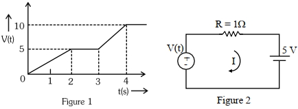
- 3For the circuit shown, the value of current at time ${t}=3.2\, {s}$ will be ...... ${A}$.View Solution
[Voltage distribution $V(t)$ is shown by Fig. $(1)$ and the circuit is shown in Fig. $(2)$]
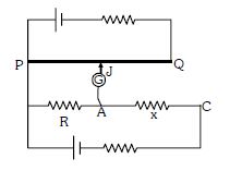
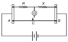
- 4Circuit for the measurement of resistance by potentiometer is shown. The galvanometer is first connected at point $A$ and zero deflection is observed at length $P J = 10\ cm$ . In second case it is connected at point $C$ and zero deflection is observed at a length $30\ cm$ from $P$ . Then the unknown resistance $X$ isView Solution
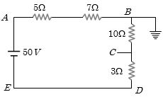
- 5In the circuit shown, the point ‘$B$’ is earthed. The potential at the point ‘$A$’ is ............. $V$View Solution
- 6The figure shows a network of five resistances and two batteries The total electrical power consumed by the circuit is ............... $W$View Solution
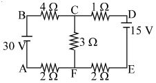
- 7Potential difference between the points $P$ and $Q$ in the electric circuit shown is ................. $V$View Solution
- 8In the meter bridge shown, the resistance $X$ has a negative temperature coefficient of resistance. Neglecting the variation in other resistors, when current is passed for some time, in the cirucit, balance point should shift towards.View Solution
- 9Resistors of $1$, $2$, $ohm$ are connected in the form of a triangle. If a $1.5\, volt$ cell of negligible internal resistance is connected across $3\, ohm$ resistor, the current flowing through this resistance will be ................ $amp$View Solution
- 10An electrical power line, having a total resistance of $2 \Omega$, delivers $1 \,kW$ at $220\, V$. The efficiency of the transmission line is approximately $.......\%$View Solution