The resistivity of alloys $ = {R_{{\rm{alloy}}}}$; the resistivity of constituent metals ${R_{{\rm{metal}}}}$. Then, usually
Easy
Download our app for free and get started
In the case of alloys the ions of one material is randomly attached to another ion/ atom of the other material. there is no definite crystal lattice like structure. Hence conduction be tough and thus they have high resistivity.

Download our appand get started for free
Experience the future of education. Simply download our apps or reach out to us for more information. Let's shape the future of learning together!No signup needed.*
Similar Questions
- 1Voltmeters $V_1$ and $V_2$ are connected in series across a $D.C.$ line. $V_1$ reads $80\, volts$ and has a per volt resistance of $200 \,\Omega$. $V_2$ has a total resistance of $32 \,kilo-ohms$. The line voltage is .............View Solution
- 2There are $n$ similar conductors each of resistance $R$. The resultant resistance comes out to be $x$ when connected in parallel. If they are connected in series, the resistance comes out to beView Solution
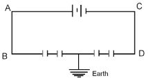
- 3Four equal capacitors are connected to a battery as shown in the adjoining figure. The potential of $A$ and $B$ areView Solution
- 4An electric fan and a heater are marked as $100\, watt$, $220\, volt$ and $1000\, watt$, $220\, volt$ respectively. The resistance of the heater isView Solution
- 5An electrical circuit consists of ten $100 \,\Omega$ resistors. Out of these $10$ resistors, a group of $n _1$ resistors are connected in parallel and another group of $n _2$ resistors are separately connected in parallel. These two groups are then connected in series and this combination is connected to a voltage source of $100 \,V$. If the net current though the circuit is $2.5 \,A$. The values of $n _1$ and $n _2$ areView Solution
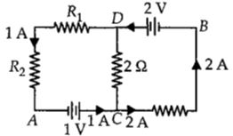
- 6In the circuit shown in the figure, if the potential at point $A$ is taken to be zero, the potential at point $B$ is ................ $V$View Solution
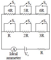
- 7Say switches $S_1, S_2$ and so on upto $S_6$ are closed, one after other in order (first $S_1$, then $S_2$) at regular intervals of $1$ minute starting from $t = 0$. The graph of current versus time is best represented asView Solution
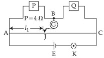
- 8Resistance are connected in a meter bridge circuit as shown in the figure. The balancing length $l_{1}$ is $40\,cm$. Now an unknown resistance $x$ is connected in series with $P$ and new balancing length is found to be $80\,cm$ measured from the same end. Then the value of $x$ will be $.......\Omega$View Solution
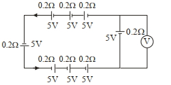
- 9The reading in the ideal voltmeter $(V)$ shown in the given circuit diagram is :View Solution
- 10In a potentiometer circuit a cell of $EMF$ $1.5\, {V}$ gives balance point at $36\, {cm}$ length of wire. If another cell of $EMF$ $2.5\, {V}$ replaces the first cell, then at what length of the wire, the balance point occurs ? (in $cm$)View Solution