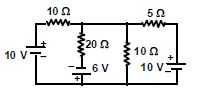
The value of current through the $20\,\Omega $ resistor is ............ $amp$
Medium


Download our appand get started for free
Experience the future of education. Simply download our apps or reach out to us for more information. Let's shape the future of learning together!No signup needed.*
Similar Questions
- 1$A\,\,{5\,^o}C$ rise in the temperature is observed in a conductor by passing some current. When the current is doubled, then rise in temperature will be equal to ............. $^oC$View Solution
- 2The resistance of a wire is$10\,\Omega $. Its length is increased by $10\%$ by stretching. The new resistance will now be .......... $\Omega$View Solution
- 3Two wires have resistance of $2$ $\Omega$ and $4$ $\Omega$ connected to same voltage, ratio of heat dissipated at resistance isView Solution
- 4View SolutionWhich of the following will NOT be observed when a multimeter (operating in resistance measuring mode) probes connected across a component, are just reversed?
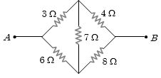
- 5Calculate the net resistance of the circuit between $A$ and $B$View Solution
- 6Assertion $(A):$ In a meter bridge experiment, null point for an unknown resistance is put inside an enclosure maintained at a higher temperature. The null point can be obtained at the same $p$ as before by decreasing the value of the standard resistance.View Solution
Reason $(R):$ Resistance of metal increases with increase in temperature.
- 7A $3\,^oC$ rise in temperature is observed in a conductor by passing a certain current. When the current is doubled, the rise in temperature will be ............. $^oC$View Solution
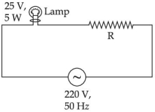
- 8A $220 \; V , 50 \; Hz$ AC source is connected to a $25 \; V$, $5 \; W$ lamp and an additional resistance $R$ in series (as shown in figure) to run the lamp at its peak brightness, then the value of $R$ (in ohm) will beView Solution
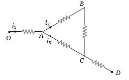
- 9The current in the arm $CD$ of the circuit will beView Solution
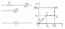
- 10In the circuit shown below (on the left) the resistance and the emf source are both variable. The graph of seven readings of the voltmeter and the ammeter ( $V$ and $I$, respectively) for different settings of resistance and the emf, taken at equal intervals of time $\Delta t$, are shown below (on the right) by the dots connected by the curve $E F G H$. Consider the internal resistance of the battery to be negligible and the voltmeter an ammeter to be ideal devices. (Take, $R_0 \equiv \frac{V_0}{I_0}$ ).View Solution
Then, the plot of the resistance as a function of time corresponding to the curve $E F G H$ is given by