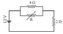
The value of the resistance $R$ in figure is adjusted such that power dissipated in the $2\,\Omega $ resistor is maximum. Then the power dissipated in the $2\,\Omega $ will be ................ $W$
Medium
Download our app for free and get started
for max. power in $2\, \Omega, \mathrm{R} \rightarrow 0$
$\mathrm{i}=\frac{12}{2}=6 \mathrm{\,A}$
$P=i^{2} R=36 \times 2=72 \mathrm{\,W}$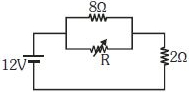

Download our appand get started for free
Experience the future of education. Simply download our apps or reach out to us for more information. Let's shape the future of learning together!No signup needed.*
Similar Questions
- 1A $25\, watt$, $220\, volt$ bulb and a $100\, watt$, $220\, volt$ bulb are connected in parallel across a $220\, volt$ line. Which bulb will glow more brightlyView Solution
- 2A cell $E _{1}$ of $emf 6 V$ and internal resistance $2 \Omega$ is connected with another cell $E _{2}$ of $emf 4 V$ and internal resistance $8 \Omega$ (as shown in the figure). The potential difference across points $X$ and $Y$ is............ $V$View Solution

- 3The electric field $E$, current density $J$ and conductivity $\sigma$ of a conductor are related asView Solution
- 4The drift velocity of free electrons in a conductor is ‘$v$’ when a current ‘$i$’ is flowing in it. If both the radius and current are doubled, then drift velocity will beView Solution
- 5There are two electric bulbs of $40\, W$ and $100\, W$. Which one will be brighter when first connected in series and then in parallel,View Solution
- 6A wire of resistance $R$ and radius $r$ is stretched till its radius became $r / 2$. If new resistance of the stretched wire is $x R$, then value of $x$ is $\qquad$View Solution
- 7A wire of length $10 \mathrm{~cm}$ and radius $\sqrt{7} \times 10^{-4} \mathrm{~m}$ connected across the right gap of a meter bridge. When a resistance of $4.5 \ \Omega$ is connected on the left gap by using a resistance box, the balance length is found to be at $60 \mathrm{~cm}$ from the left end. If the resistivity of the wire is $\mathrm{R} \times 10^{-7} \Omega \mathrm{m}$, then value of $\mathrm{R}$ is :View Solution
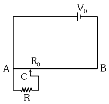
- 8The sliding contact $C$ is at one fourth of the length of the potentiometer wire $( AB )$ from $A$ as shown in the circuit diagram. If the resistance of the wire $AB$ is $R _0$, then the potential drop $( V )$ across the resistor $R$ isView Solution
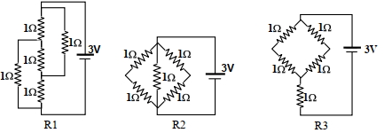
- 9Figure shows three resistor configurations $\mathrm{R} 1, \mathrm{R} 2$ and $\mathrm{R} 3$ connected to $3 \mathrm{~V}$ battery. If the power dissipated by the configuration $\mathrm{R} 1, \mathrm{R} 2$ and $\mathrm{R} 3$ is $\mathrm{P} 1, \mathrm{P} 2$ and $\mathrm{P} 3$, respectively, thenView Solution
Figure:
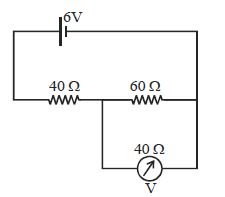
- 10The reading of voltmeter in the circuit shown is ............. $V$View Solution