When a resistance of $2\,ohm$ is connected across the terminals of a cell, the current is $0.5$ amperes. When the resistance is increased to $5\, ohm$, the current is $0.25\, amperes$. The internal resistance of the cell is ............. $ohm$
Medium


Download our appand get started for free
Experience the future of education. Simply download our apps or reach out to us for more information. Let's shape the future of learning together!No signup needed.*
Similar Questions
- 1A $10\,m$ long potentiometer wire has a potential gradient of $0.0025\, V/cm$. Calculate the distance of null point when the wire is connected to a $1.025\,V$ standard cell ............... $\mathrm{m}$View Solution
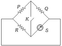
- 2In the following Wheatstone bridge $P/Q = R/S$. If key $K$ is closed, then the galvanometer will show deflectionView Solution
- 3View SolutionOn increasing the temperature of a conductor, its resistance increases because
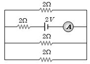
- 4View SolutionThe reading of the ammeter as per figure shown is
- 5Space between two concentric conducting spheres of radii $a$ and $b (b > a)$ is filled with $a$ medium of resistivity $\rho $. The resistance between the two spheres will beView Solution
- 6There are $8$ equal resistances $R$. Two are connected in parallel, such four groups are connected in series, the total resistance of the system will beView Solution
- 7The emf of a battery is $2\, V$ and its internal resistance is $0.5 \,\Omega$. The maximum power which it can deliver to any external circuit will be ............. $watt$View Solution
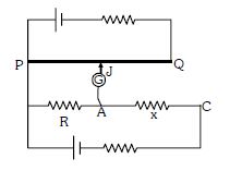
- 8Circuit for the measurement of resistance by potentiometer is shown. The galvanometer is first connected at point $A$ and zero deflection is observed at length $P J = 10\ cm$ . In second case it is connected at point $C$ and zero deflection is observed at a length $30\ cm$ from $P$ . Then the unknown resistance $X$ isView Solution
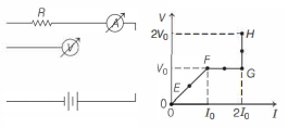
- 9In the circuit shown below (on the left) the resistance and the emf source are both variable. The graph of seven readings of the voltmeter and the ammeter ( $V$ and $I$, respectively) for different settings of resistance and the emf, taken at equal intervals of time $\Delta t$, are shown below (on the right) by the dots connected by the curve $E F G H$. Consider the internal resistance of the battery to be negligible and the voltmeter an ammeter to be ideal devices. (Take, $R_0 \equiv \frac{V_0}{I_0}$ ).View Solution
Then, the plot of the resistance as a function of time corresponding to the curve $E F G H$ is given by
- 10The charge flowing through a resistance $R$ varies with time $t$ as $ Q=at-bt^2 $ where $a$ and $b$ are positive constants . The total heat produced in $R$ isView Solution