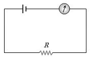
Which of the following wiring diagrams could be used to experimentally determine $R$ using ohm's law? Assume an ideal voltmeter and an ideal ammeter.
- A

- B

- C

- D

Medium


Download our appand get started for free
Experience the future of education. Simply download our apps or reach out to us for more information. Let's shape the future of learning together!No signup needed.*
Similar Questions
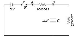
- 1When the key $K$ is pressed at time $t = 0$, which of the following statements about the current $I$ in the resistor $AB$ of the given circuit is trueView Solution
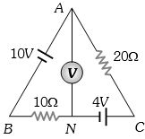
- 2The reading of the ideal voltmeter in the adjoining diagram will be ................. $V$View Solution
- 3Forty electric bulbs are connected in series across a $220\, V$ supply. After one bulb is fused, the remaining $39$ are connected again in series across the same supply. The illumination will beView Solution
- 4If $n, e, \tau$ and $m$ are representing electron density, charge, relaxation time and mass of an electron respectively, then the resistance of a wire of length / and cross-sectional area $A$ is given byView Solution
- 5Find the charge on the capacitor $C$ in the following circuit ............ $\mu C$View Solution
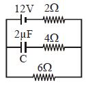
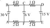
- 6The figure shows a network of four resistances and three batteries The electrical power dissipated as heat is .............. $W$View Solution
- 7For driving a current of $2\, A$ for $6$ minutes in a circuit, $1000\, J$ of work is to be done. The $e.m.f.$ of the source in the circuit is ................ $V$View Solution
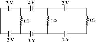
- 8View SolutionIn the below circuit the current in each resistance is
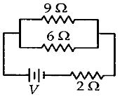
- 9If power dissipated in the $9 \,\Omega$ resistor in the circuit shown is $36\,W$, the potential difference across the $2 \,\Omega$ resistor is .......... $V$View Solution
- 10A battery of $e.m.f.$ $10\, V$ and internal resistance $3\,\Omega $ is connected to a resistor as shown in the figure. If the current in the circuit is $0.5\, A$. then the resistance of the resistor will be ............. $\Omega$View Solution