Questions

Answer the questions.[Phy-5M]

🎯

Test yourself on this topic

47 questions · timed · auto-graded

Question 15 Marks
When a 12 V battery is connected across an unknown resistor, there is a current of 2.5 mA in the circuit. Find the value of the resistance of the resistor.
Answer
$\text{V}=\text{IR}\Rightarrow \ \text{R}=\frac{\text{V}}{\text{I}}$

$\Rightarrow \ \text{R}=\frac{12}{2.5\times10^{-3}}=4800 \ \Omega=4.8 \ \text{K}\Omega$.

View full question & answer
Question 25 Marks
A copper wire has diameter 0.5 mm and resistivity of 1.6 × 10⁻⁸ Ω m. What will be the length of this wire to make its resistance 10 Ω? How much does the resistance change if the diameter is doubled?
Answer
Area of cross-section of the wire, $\text{A}=\pi\Big(\frac{\text{d}}{2}\Big)2$

Diameter= 0.5 mm = 0.0005m

Resistance, $\text{R}=10\Omega$

We know that

$\text{R}=\rho\frac{\text{l}}{\text{A}}$

$\text{l}=\frac{\text{RA}}{\rho}$

$=\frac{10\times3.14\times\Big(\frac{0.0005}{2}\Big)^2}{1.6\times10^{-8}}$

$=\frac{10\times3.14\times25}{4\times1.6}=122.72\text{m} $

$\therefore$ length of the wire = 122.72m

if the diameter of the wire is doubled, new diameter = 2 × 0.5 = 1 mm = 0.001 m

Let new resistance be R'

$\text{R}'=\rho\frac{\text{l}}{\text{A}}$

$=\frac{1.6\times10^{-8}\times122.72}{\pi\Big(\frac{1}{2}\times10^{-3}\Big)^2}$

$=\frac{1.6\times10^{-8}\times122.72\times4}{3.14\times10^{-6}}$

$=250.2\times10^{-2}=2.5 \ \Omega$

View full question & answer
Question 35 Marks
Explain with the help of a labelled circuit diagram how you will find the resistance of a combination of three resistors, of resistance R1, R2 and R3, joined in parallel. Also mention how you will connect the ammeter and the voltmeter in the circuit when measuring the current in the circuit and the potential difference across one of the three resistors of the combination.
Answer


Let the resistance of the three resistors be R1, R2 and R3, respectively. Let their combined resistance be R. Let the total current flowing in the circuit be I and the strength of the battery is V. Then from Ohm's law, we have:

V = IR .....(i)

We know that when the resistors are connected in parallel, the potential drop across each resistance is the same.

Therefore:

I = I1 + I2 + I3

$\text{I}=\frac{\text{V}}{\text{R}_1}+\frac{\text{V}}{\text{R}_2}+\frac{\text{V}}{\text{R}_3}$

$\text{I}=\frac{\text{V}}{\Big(\frac{1}{\text{R}_1}+\frac{1}{\text{R}_2}+\frac{1}{\text{R}_3}\Big)}\ .....(\text{ii})$

From equations (1) and (2) we have:

$\frac{1}{\text{R}}=\frac{1}{\text{R}_1}+\frac{1}{\text{R}_2}+\frac{1}{\text{R}_3}$

  1. Ammeter is connected in series with the resistor.
  2. Voltmeter is connected in parallel with the resistor.
View full question & answer
Question 45 Marks
Derive the expression for the heat produced due to a current ‘I’ flowing for a time interval ‘t’ through a resistor ‘R’ having a potential difference ‘V’ across its ends. With which name is the relation known? How much heat will an instrument of 12W produce in one minute if it is connected to a battery of 12V?
Answer
  1. Work done in moving the charge W = VQ

Power input,

 $\text{P} = \frac{VQ}{t}$

$= {VI}$

$\therefore \text{Eergy, E = P}\times t = \text{V I t}$

This energy gets dissipated in the form of heat.

$\therefore \text{H = V I t}$

Applying Ohm's law, we get,

$H = \text{I}^{2}Rt$

  1. The relation is known as Joule's law of heating.
  2. $\text{P = 12 W} {\text{ t = 1 minute = 60s}}$

$H = P \times t$

$\text{= 12 W} \times \text{60s}$

$\text{H = 720 J}$

View full question & answer
Question 55 Marks
  1. What is meant by saying that the potential difference between two points is 1 volt? Name a device that helps to measure the potential difference across a conductor.
  2. Why does the connecting cord of an electric heater not glow hot while the heating element does?
  3. Electrical resistivities of some substances at $20^{0}\text{C}$ are given below:
Silver $1.60\times10^{-8} \Omega \text{ m}$
Copper $1.62\times10^{-8} \Omega \text{ m}$
Tungsten $5.20\times10^{-8} \Omega \text{ m}$
Iron $10.0\times10^{-8} \Omega \text{ m}$
Mercury $94.0\times10^{-8} \Omega \text{ m}$
Nichrome $100\times10^{-6} \Omega \text{ m}$

Answer the following questions in relation to them:

  1. Among silver and copper, which one is a better conductor? Why?
  2. Which material would you advise to be used in electrical heating devices? Why?
Answer
  1. When 1 joule of work is done to move a charge of 1 coulomb from one point to another.

Device - Voltmeter.

  1. The heating element of the heater is made up of alloy which has very high resistance so when current flows through the heating element, it becomes too hot and glows red. But the resistance of cord which is usually of copper or aluminum is very law so it does not glow.
  2.  
  1. Silver is the best conductor of electricity and heat among all metals as it has more number of free electrons in the outermost shell. Its resistivity (1.60 × 10-8 Ωm) is less than copper (1.62 × 10-8 Ωm). Of couse, silver is the best conductor of electricity. Still, we find use of copper on a large scale in domestic wiring because silver is quite expensive.

  2. Nichrome is the best material for heating elements. It is because the resistivity of the nichrome is more than the resistivities of the metals used to make it and it does not oxidise at higher temperature.

View full question & answer
Question 65 Marks
View full question & answer
Question 75 Marks
  1. With the help of a suitable circuit diagram prove that the reciprocal of the equivalent resistance of a group of resistances joined in parallel is equal to the sum of the reciprocals of the individual resistances.
  2. In an electric circuit, two resistors of $12\Omega$ each are joined in parallel to a 6V battery. Find the current drawn from the battery.
Answer
  1.  


Let there are n resistances, each of value R1, R2......Rn, respectively, are connected in parallel to a battery of voltage V. if the equivalent resistance of the circuit is Req, then current drawn from $\text{i}=\frac{\text{V}}{\text{R(eq)}}$the battery is:

The total current i then divides into i1, i2, i3.....in, respectively in the given resistors.

As all the resistances are connected in parallel, hence the voltage across each resistor is V volt. 

Now we can write,

$\text{i}=\text{i}_1+\text{i}_2+\text{i}_3+\ ...\ +\text{i}_\text{eq}$

$\frac{\text{V}}{\text{R(eq)}}=\frac{\text{V}}{\text{R}_1}+\frac{\text{V}}{\text{R}_2}+\frac{\text{V}}{\text{R}_3}+\ ...\ +\frac{\text{V}}{\text{R}_\text{n}}\dots(1)$

From equation 1,

$\frac{1}{\text{R(eq)}}=\frac{1}{\text{R}_1}+\frac{1}{\text{R}_2}+\frac{1}{\text{R}_3}+\ ...\ +\frac{1}{\text{R}_\text{n}}$

Hence, reciprocal of the equivalent resistance is equal to the sum of reciprocal of each resistor joined in parallel.

  1. Let net resistance of the given parallel combination be Rnet, Then,

$\frac{1}{\text{R}_\text{net}}=\frac{1}{12}+\frac{1}{12}$

$\frac{1}{\text{R}_\text{net}}=\frac{2}{12}=\frac{1}{6}$

$\Rightarrow\ \text{R}_\text{net}=6\Omega$

Hence, current, $\text{i}=\frac{\text{V}}{\text{R}_\text{net}}=\frac{6\text{V}}{6\Omega}=1\text{A}$

View full question & answer
Question 85 Marks
An electric lamp of resistance $20\Omega$ and a conductor of resistance $4\Omega$ are connected to a 6V battery as shown in the circuit. Calculate:

  1. The total resistance of the circuit,
  2. The current through the circuit,
  3. The potential difference across the (i) electric lamp and (ii) conductor, and
  4. Power of the lamp.
Answer


Resistance of electric lamp $=20\Omega$

Resistance of Conductor $=4\Omega$

Voltage of Battery = 6V

  1. The total resistance of the circuit $=20\Omega+4\Omega=24\Omega$
  2. Current in the circuit = I

Applying Ohm's law in the circuit,

$\text{V}=\text{IR}$

$6\text{V}=\text{I}\times24\Omega$

$\text{I}=\frac{6\text{V}}{24\Omega}=0.25\text{A}$

Hence current in the circuit is 0.25 Ampere.

  1. Potential difference across lamp,

$\text{V}_\text{lamp}=\text{IR}$

$\text{V}_\text{lamp}=0.25\text{A}\times20\Omega=5\text{V}$

$\therefore\ \text{V}_\text{lamp}=5\text{V}$

Potential difference across conductor,

$\text{V}_\text{Conductor}=\text{IR}$

$\text{V}_\text{Conductor}=0.25\text{A}\times4\Omega=1\text{V}$

$\therefore\ \text{V}_\text{Conductor}=1\text{V}$

  1. Power of Lamp $=\text{I}^2\text{R}=(0.25)^2\times20=1.25\text{W}$
View full question & answer
Question 95 Marks
What is a solenoid? Draw the pattern of magnetic field lines of:
  1. A current carrying solenoid.
  2. A bar magnet. List two distinguishing features between the two fields.
Answer
A solenoid is a long cylindrical coil of wire consisting of a large no. of turns bound together very tightly.
  1.  


  1.  


Two distinguishing features between the two fields:
  1. Magnetic field of the solenoid can be varied as per our requirements just by changing the current or core of the solenoid whereas the magnetic field of the bar magnet is fixed.
  2. Magnetic field outside the solenoid is negligible as compared to the bar magnet.
View full question & answer
Question 105 Marks
You are given three resistances of 1,2 and 3 ohms. Show by diagrams, how with the help of these resistances you can get:

  1. $6\Omega$

  2. $\frac{6}{11}\Omega$

  3. $1.5\Omega$

Answer


Equivalent resistance $=1\Omega+2\Omega+3\Omega=6\Omega$


Equivalent resistance
$\frac{1}{\text{R}}=\frac{1}{1}+\frac{1}{2}+\frac{1}{3}=\frac{6+3+2}{6}=\frac{11}{6}$

$\therefore\text{R}=\frac{6}{11}\Omega$


Equivalent resistance of first line

$=1\Omega+2\Omega=3\Omega$

Resistance of the secound line $=3\Omega$

Equivalent resistance

$\frac{1}{\text{R}}=\frac{1}{3}+\frac{1}{3}=\frac{2}{3}$

$\therefore\text{R}=\frac{3}{2}=1.5\Omega$

View full question & answer
Question 115 Marks
With the help of a diagram, derive the formula for the resultant resistance of three resistors connected in series.
Answer


Fig shows three resistance R1, R2 and R3 connected in series with a battery of V volts.

Lets the p.d. across R1, R2 and R3 is V1, V2 and V3 respectively.

s.t. V = V1 + V3 + V2 .........(1)

Let the equivalent resistance be R and current flowing through whole circuit is 1.

By ohm's law

$\frac{\text{V}}{\text{I}}=\text{R}$

V = I × R .....(2)

Applying ohm's law to both R1, R2 and R3.

V1 = I × R1 ......(3)

V2 = I × R2 ..........(4)

V3 = I × R3 ......(5)

From eq. (1), (2), (3), (4) and (5), we get

I × R = I × R1 + I × R2 + I × R3

I × R = I × (R1 + R2 + R3)

R = R1 + R2 + R3

View full question & answer
Question 125 Marks
With the help of a circuit diagram, deduce the equivalent resistance of two resistances connected in series.

Two resistances are connected in series as shown in the diagram:


  1. What is the current through the 5 ohm resistance?
  2. What is the current through R?
  3. What is the value of R?
  4. What is the value of V?
Answer
Fig shows two resistance R1 and R2 connected in series with a battery of V volt.
Let the p.d. across R1 is V1 and the p.d. across R2 is V2.
s.t. V = V1 + V2 ......(1)
Let the equivalent resistance be R and current flowing through whole circuit is 1.
By ohm's law's,
$\frac{\text{V}}{\text{I}}=\text{R}$
V = I × R .........(2)
Applying ohm's law to both R1 and R2
V1 = I × R1 ......(3)
V2 = I × R2 .......(4)
From eqs. (1), (2), (3) and (4), we get
I × R = I × R1 + I × R2
I × R = I × (R1 + R2)
R = R1 + R2
View full question & answer
Question 135 Marks
When a high resistance voltmeter is connected directly across a resister its reading is 2V. An electric cell is sending the current of 0.4 A, (measured by an ammeter) in the electric circuit

in which a rheostat is also connected to vary the current.

  1. Draw an equivalent labelled circuit for the given data.

  2. Find the resistance of the resister.

  3. Name and state the law applicable in the given case. A graph is drawn between a set of values of potential difference (v) across the resister and current (I) flowing through it.

Show nature of graph thus obtained.

View full question & answer
Question 145 Marks
What is Joule’s heating effect? How can it be demonstrated experimentally? List its four applications in daily life.
Answer
The Joule’s Law of Heating states that the heat produced in a resistor is:

  1. Directly proportional to the square of current for a given resistor.
  2. Directly proportional to resistance for a given current, and
  3. Directly proportional to the time for which the current flows through the resistor.

This can be expressed by following equation:

H = I2Rt

Here; I is electric current, R is resistance, t is time and H is heating effect.

Experiment to Demonstrate Joule’s Law of Heating:

  • In this experiment, we will show the effect of current on heating.
  • Take a water heating immersion rod and connect to a socket which is connected to regulator. It is important to recall that a regulator controls the amount of current flowing through a device.
  • Keep the pointer of regulator on minimum and count the time taken by immersion rod to heat a certain amount of water.
  • Increase the pointer of regulator to next level. Count the time taken by immersion rod to heat the same amount of water.
  • Repeat above step for higher levels on regulator to count the time.
​​​​​​​Observation: It is seen that with increased amount of electric current, less time is required to heat the same amount of water. This shows Joule’s Law of Heating.

Application: Electric toaster, oven, electric kettle and electric heater etc. work on the basis of heating effect of current.

View full question & answer
Question 155 Marks
What is electrical resistivity of a material? What is its unit? Describe an experiment to study the factors on which the resistance of conducting wire depends.
Answer
The inherent property of a conductor because of which it resists the flow of electric current is called resistivity. Resistivity for a particular material is unique. The SI unit of resistivity is (Ohm metre).

Experiment to study the factors on which resistance of conducting wire depends:

  • Take an ammeter, electric cell, plug key, nichrome wire and wires of different materials.
  • Make the circuit as shown in figure.
  • Start the experiment with nichrome wire. Attach it in the circuit and take ammeter reading.
  • Change the length of nichrome wire and take ammeter reading.
  • Change the thickness of nichrome wire and take ammeter reading.
  • After above steps, use copper wire for the experiment. Attach a copper wire in the circuit and take ammeter reading.
  • Change the length of copper wire and take ammeter reading.
  • Change the thickness of copper wire and take ammeter reading.
  • Repeat above steps with wires of different materials.

Observations:

  • It is seen that resistance depends on material of conductor.
  • Resistance depends on length of conductor.
  • Resistance depends on area of cross-section.
View full question & answer
Question 165 Marks
Two resistors, with resistances $ 5 Ω$ and $10 Ω$ respectively are to be connected to a battery of emf 6V so as to obtain:
  1. Minimum current flowing.
  2. Maximum current flowing.
  1. How will you connect the resistances in each case?
  2. Calculate the strength of the total current in the circuit in the two cases.
Answer
Given: Two resistors with resistances R1 = 5 ohm and R2 = 10 ohm, V = 6 volt

  1. For minimum current these two should be connected in series. For maximum current these two should be connected in parallel.
  1. In series,

Total resistance = 5 + 10 = 15 ohms

Therefore total current drawn $= \frac{\text{V}}{\text{R}}=\frac{6}{15}=0.4\ \text{amps}$

In parallel,

Total resistance R is given as

$\frac{1}{\text{R}}=\frac{1}{\text{R}_1}+\frac{1}{\text{R}_2}$

$\frac{1}{\text{R}}=\frac{1}{5}+\frac{1}{10}$

$\frac{1}{\text{R}}=\frac{3}{10}$

$\text{R}=\frac{10}{3}\ \text{ohm}$

Therefore total current drawn by the circuit $=\frac{\text{V}}{\text{R}}=\frac{6}{\big(\frac{10}{3}\big)}=1.8\ \text{amps}.$

View full question & answer
Question 175 Marks
Two lamps, one rated 40W at 220V and the other 60W at 220V, are connected in parallel to the electric supply at 220V.
  1. 10 Draw a circuit diagram to show the connections.
  2. Calculate the current drawn from the electric supply.
  3. Calculate the total energy consumed by the two lamps together when they operate for one hour.
Answer
Given 2 Lamps: P1 = 40W, P2 = 60W
V= 220V

Voltage across both the bulbs is same and is equal to 220V.
Current through 40W lamp $=\text{I}_1=\frac{\text{P}_1}{\text{V}}=\frac{40}{220}\text{A}$
Current through 60W lamp $=\text{I}_2=\frac{\text{P}_2}{\text{V}}=\frac{60}{220}\text{A}$
Total current drawn from the electric supply $=\frac{40}{220}+\frac{60}{220}=0.45\text{A}$
Energy consumed by 40 W lamp in 1hr. E1 = P1 × t = 40 × 1 = 40Wh
1Wh = 3.6kJ
E1 = 40 × 3.6 = 144KJ
Energy consumed by 60W lamp in 1 hr, E2 = p2 × t = 60 × 1 = 60Wh = 216KJ
Total energy consumed = 144 + 216 = 360KJ
View full question & answer
Question 185 Marks
Three $2\Omega$ resistors, A, B and C, are connected as shown in Figure. Each of them dissipates energy and can withstand a maximum power of 18W without melting. Find the maximum current that can flow through the three resistors?


Answer
Here, P = 18W

Using, P = I2R, we get

$\text{I}=\sqrt{\frac{\text{P}}{\text{R}}}=\sqrt{\frac{18}{2}}=\sqrt{9}=3\text{A}$

$\therefore$ Maximum current that can flow through a resistor A = 3A


Since resistors B and C are connected in parallel, so potential difference across B and C is same. Let I1, be the current flowing through resistor. B and I2 be the current flowing through resistor C,

$\therefore$ I1R1 = I2R2

or $\frac{\text{I}_1}{\text{I}_2}=\frac{\text{R}_2}{\text{R}_1}=\frac{2\Omega}{2\Omega}=1$

or, I1 = I2

But I1 + I2 = I = 3

$\therefore$ 2I1 = 3 or I1 = 1.5A

and I2 = I1 = 1.5A

View full question & answer
Question 195 Marks
Three resistors are connected as shown in the diagram.

Through the resistor 5 ohm, a current of 1 ampere is flowing,
  1. What is the current through the other two resistors?
  2. What is the p.d. across AB and across AC?
  3. What is the total resistance?
Answer


According to the diagram

  1. Total current I = 1 amp is entering the parallel combination of R1 and R. Let I1 current flows through R1 and I2 current flows through R2

Then

$\text{I}_1=\frac{\text{IR}_2}{\text{R}_1+\text{R}_2}$

$=\frac{1\times15}{10+15}=0.6\text{A}$

$\text{I}_2=\frac{\text{IR}_2}{\text{R}_1+\text{R}_2}$

$=\frac{1\times10}{10+15}=0.4\text{A}$

  1. p.d. across AB = IR3 = 1 × 5 = 5V

Equivalent resisyance between B and C is

$\frac{1}{\text{R}'}=\frac{1}{\text{R}_1}+\frac{1}{\text{R}_2}=\frac{1}{10}+\frac{1}{15}$

$\frac{1}{\text{R}'}=\frac{5}{30}$

R' = 6 ohm

Total resistance between A and C is R = 5 + 6 = 11 ohm

p.d. across AC = IR = 1 × 11 = 11V

  1. Total resistance = R3 + R' = 5 + 6 = 11 ohm.
View full question & answer
Question 205 Marks
Three incandescent bulbs of 100W each are connected in series in an electric circuit. In another circuit another set of three bulbs of the same wattage are connected in parallel to the same source.
  1. Will the bulb in the two circuits glow with the same brightness? Justify your answer.
  2. Now let one bulb in both the circuits get fused. Will the rest of the bulbs continue to glow in each circuit? Give reason.
Answer
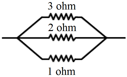
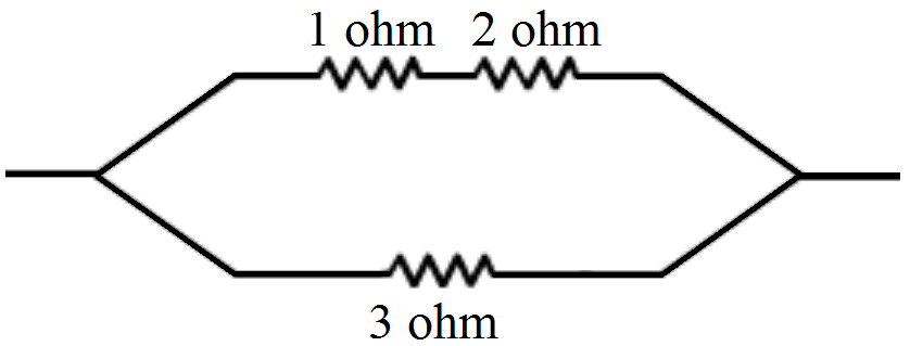
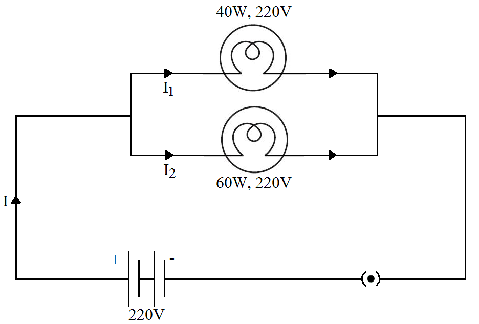
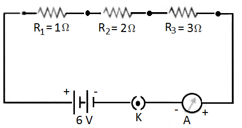
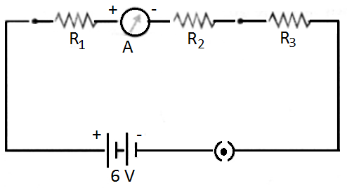
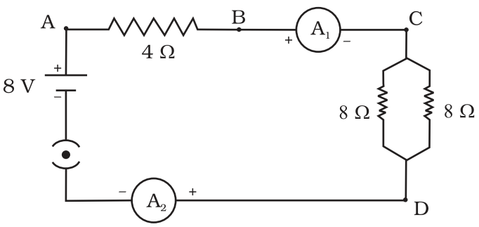
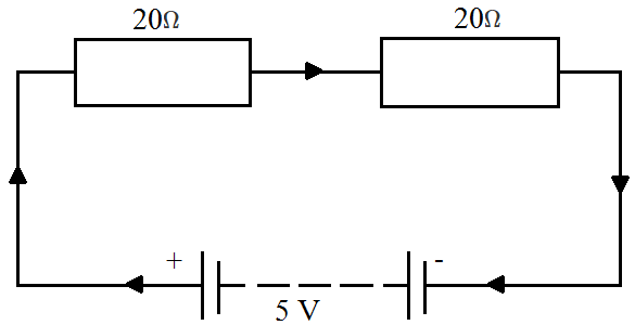
  1. The two situations given in questions is shown in the figure given below:


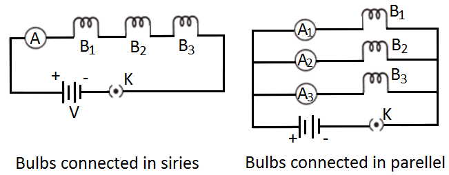
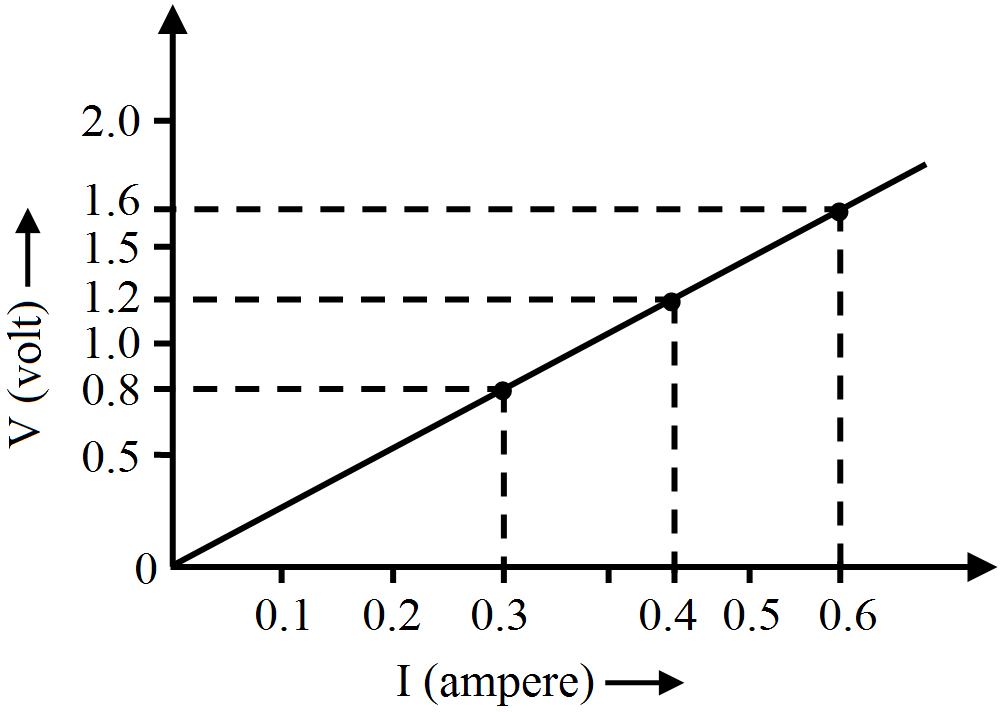
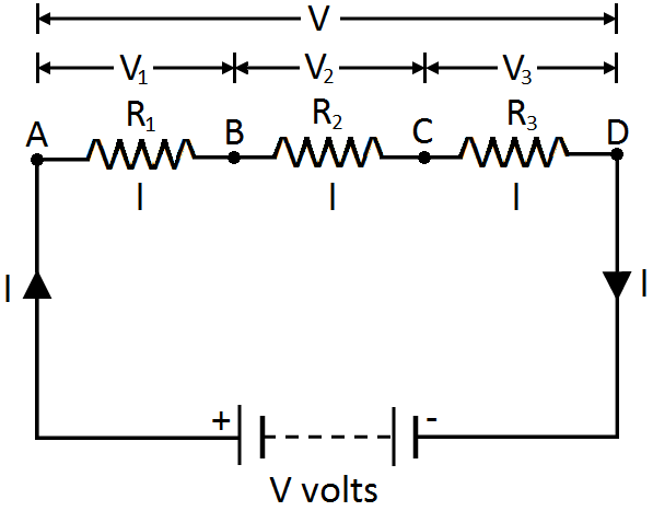
Let us assume that the resistance of each bulb is R and potential difference is V

Equivalent resistance in series combination = Req = R + R + R = 3R.

Let current through each bulb in series combination be I1.

Now, $\text{V}=\text{I}_1\times3\text{R}\Rightarrow\ \text{I}_1=\frac{\text{V}}{3\text{R}}$

Now, power consumption across each bulb in series combination is,

$\text{P}_1=\text{I}^2_1(3\text{R})=\Big(\frac{\text{V}}{3\text{R}}\Big)^2\times3\text{R}$

$=\frac{\text{V}^2}{9\text{R}^2}\times3\text{R}=\frac{\text{V}^2}{3\text{R}}\ ....(\text{i})$

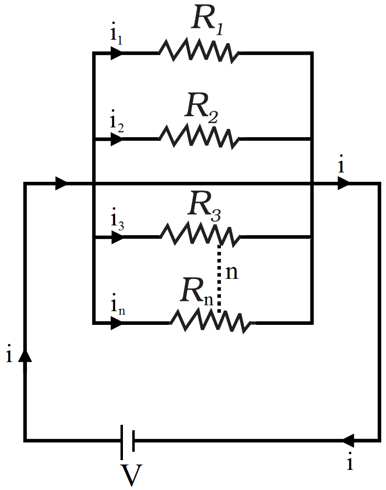
In case of parallel circuit,

Resistance of each bulb = R and

Voltage across each bulb = V

$\therefore$ Power consumption of each bulb in parallel combination is

$\text{P}_2=\frac{\text{V}^2}{\text{R}}\ ....(\text{ii})$

From eq. (i) and (ii), we have, $\frac{\text{P}_1}{\text{P}_2}=\frac{\Big(\frac{\text{V}^2}{3\text{R}}\Big)}{\Big(\frac{\text{V}^2}{\text{R}}\Big)}\Rightarrow\ \text{P}_2=3\text{P}_1.$

So, brightness of each bulb in parallel combination will increase. Each bulb will glow 3 times brighter to that of each bulb in series combination.

  1. If one bulb gets fused in series combination then, circuit gets broken and current stops flowing and remaining bulb don't glow.

If one bulb gets fused in series combination then, same voltage continue to act on the remaining voltage and hence, other bulbs continue to glow with same brightness.

View full question & answer
Question 215 Marks
The p.d. across a lamp is 12V. How many joules of electrical energy are changed into heat and light when:
  1. A charge of 1C passes through it?
  2. A charge of 5C passes through it?
  3. A current of 2A flows through it for 10s?
Answer
P.d. = 12V

  1. $\text{P}.\text{d}.\frac{\text{Work done}}{\text{Charge Moved}}$

Work done = P.d. × Charge moved

= 12 × 1 = 12J

Amount of electrical energy changed into heat and light = 12J

  1. Work done = P.d. × Charge moved

= 12 × 5 = 60J

Amount of electrical energy changed into heat and light = 60J

  1. $\text{I}=\frac{\text{Q}}{\text{t}}$

Q × I × t

= 2 × 10 = 20C

Work done = p.d. × Charged moved

= 12 × 20 - 240J

Amount of electrical energy changed into heat and light = 240J

View full question & answer
Question 225 Marks
The circuit diagram given below shows the combination of three resistors R1 R2 and R3:

Find:
  1. Total resistance of the circuit.
  2. Total current flowing in the circuit.
  3. The potential difference across R.
Answer
  1. Total resistance of two resistors that are connected in parallel is:

$\frac{1}{\text{R}'}=\frac{1}{3}+\frac{1}{6}$

$\frac{1}{\text{R}'}=\frac{3}{6}$

R’ = 2ohms

Total resistance of the circuit = 2 + 4 ohms = 6 ohms

  1. Total current flowing through the circuit $=\frac{\text{V}}{\text{Total resistance}}$

$\text{I}=\frac{12}{6}=2\ \text{amps}$

  1. Potential difference across R1 = R1 × I = 4 × 2 = 8V.
View full question & answer
Question 235 Marks
State whether an electric heater will consume more electrical energy or less electrical energy per second when the length of its heating element is reduced. Give reasons for your answer.
Answer
By reducing the length of element the resistance will decrease. Power is inversely proportional to resistance. So, this will result in more consumption of energy.
View full question & answer
Question 245 Marks
State Ohm's law. Write the necessary conditions for its validity. How is this law verified experimentally? What will be the nature of graph between potential difference and current for a
conductor? Name the physical quantity that can be obtained from this graph.
Answer
Ohm's law: The potential difference across the ends of a resistor is directly proportional to the current through it, provided it's temperature remains the same.
The conditions for its validity is temperature and all other parameters should be constant.
The nature of the graph is a straight line passing through the origin.
Resistance is the physical quantity that can be determined from the graph.
View full question & answer
Question 255 Marks
State Ohm’s law? How can it be verified experimentally? Does it hold good under all conditions? Comment.
Answer
According to Ohm's law the electric current flowing through a conductor is directly proportional to the potential difference applied across its ends provided the physical conditions such as temperature etc remains unchanged.LetVbe the potential difference applied across the ends of conductor through which currentIflows, then according to Ohm's law.$\text{V}\propto\text{I}\Rightarrow\ \text{V}=\text{IR}$Ohm’s law can be verified experimentally by the activity given below:
  1. Firstly, Set up a circuit as shown in figure given below, consisting of a nichrome wire XY of length, say 0.5m, an ammeter, a voltmeter and four cells of 1.5V each. (Nichrome is an alloy of nickel,chromium, manganese, and iron metals.)

  1. First use only one cell as the source in the circuit. Note the reading in the ammeterI,for the current and reading of the voltmeterVfor the potential difference across the nichrome wire XY in the circuit. Tabulate them in the Table given.
  2. Next connect two cells in the circuit and note the respective readings of the ammeter and voltmeter for the values of current through the nichrome wire and potential difference across the nichrome wire.
  3. Repeat the above steps using three cells and then four cells in the circuit separately.
  4. Calculate the ratio of V to I for each pair of potential difference V and current I.
S.No.Number of cells used in the circuitCurrent through the nichrome wire, I (ampere)Potential difference across the nichrome wire, V (Volt)$\frac{\text{V}}{\text{I}}$$\Big(\frac{\text{Volt}}{\text{Ampere}}\Big)$
1.1
2.2
3.3
4.4
  1. Plot a graph between V and I. The graph will be a straight line as shown below.

  1. This verifies the Ohm’s law.
Ohm's does not hold under all conditions as it is basically not a fundamental law which means it has exceptions. Following are the conditions when Ohm’s law does not hold:
  • It is not obeyed when physical conditions of conductors like temperature keep on changing.
  • It is not obeyed by a lamp filament, junction diode, thermistor etc.
  • It is not obeyed in case of superconductors whose resistance is equal to zero.

View full question & answer
Question 265 Marks
Show with the help of diagrams, how you would connect three resistors each of resistance $6 Ω,$ so that the combination has resistance of
  1. $9 Ω$
  2. $ 4 Ω.$
Answer
  1.  

Resultant resistance for parallel circuit = R

$\frac{1}{\text{R}}=\frac{1}{6}+\frac{1}{6}$

$\frac{1}{\text{R}}=\frac{2}{6}$

$\text{R} = 3$

Effective resistance = 6 + 3 = 9 ohms

  1.  

Resultant resistance for each parallel circuit = R

$\frac{1}{\text{R}}=\frac{1}{6}+\frac{1}{6}+\frac{1}{6}$

$\frac{1}{\text{R}}=\frac{3}{6}$

$\text{R} = 2$

Therefore effective resistance = 2 + 2 = 4 ohms.

View full question & answer
Question 275 Marks
Redraw the circuit of Question 1, putting in an ammeter to measure the current through the resistors and a voltmeter to measure the potential difference across the 12 Ω resistor. What would be the readings in the ammeter and the voltmeter?
View full question & answer
Question 285 Marks
In the circuit given below:


  1. What is the combined resistance?
  2. What is the p.d. across the combined resistance?
  3. What is the p.d. across the $3 Ω$ resistor?
  4. What is the current in the $3 Ω$ resistor?
  5. What is the current in the $6 Ω$ resistor?
Answer
Total current flowing through circuit, I = 6A

R1 = 3 ohm, R2 = 6 ohm

Combined resistance R is

$\frac{1}{\text{R}}=\frac{1}{3}+\frac{1}{6}$

$\frac{1}{\text{R}}=\frac{3}{6}$

R = 2 ohms

p.d. across the combined resistance = IR = 6 × 2 12V

p.d. across the 3 ohm resistor = p.d. across the combined resistance = 12V

 Current flowing through the 3 ohm resistor $=\frac{\text{V}}{\text{R}_1}=\frac{12}{3}=4\text{A}$

 Current flowing through the 3 ohm resistor $=\frac{\text{V}}{\text{R}_2}=\frac{12}{6}=2\text{A}$

View full question & answer
Question 295 Marks
In the circuit diagram given below, three resistors R R , and R of $5 Ω, 10 Ω$ and $30 Ω,$ respectively are connected as shown.

Calculate:
  1. Current through each resistor.
  2. Total current in the circuit.
  3. Total resistance in the circuit.
Answer
V = 12V

R1, R2 and R3 are connected in parallel.

current through $\text{R}_1=\frac{\text{V}}{\text{R}_1}=\frac{12}{5}=2.4\text{A}$

current through $\text{R}_2=\frac{\text{V}}{\text{R}_2}=\frac{12}{10}=1.2\text{A}$

current through $\text{R}_3=\frac{\text{V}}{\text{R}_2}=\frac{12}{30}=0.4\text{A}$

Total current in the circuit = 2.4 + 1.2 + 0.4 = 4A

Total resistance in the circuit = R

$\frac{1}{\text{R}}=\frac{1}{\text{R}_1}+\frac{1}{\text{R}_2}+\frac{1}{\text{R}_3}$

$\frac{1}{\text{R}}=\frac{1}{5}+\frac{1}{10}+\frac{1}{30}$

$\frac{1}{\text{R}}=\frac{10}{30}$

$\text{R}=3\ \text{ohm}$

View full question & answer
Question 305 Marks
In the circuit diagram given below five resistances of $10 Ω, 40 Ω, 30 Ω, 20 Ω\ \text{and}\ 60 Ω$ are connected as shown to a 12V battery.

Calculate:
  1. Total resistance in the circuit.
  2. Total current flowing in the circuit.
Answer
  1. Equivalent resistance of $10\Omega$ and $40\Omega$ resistance (Connected in parallel) is R1 given as:

$\frac{1}{\text{R}_1}=\frac{1}{10}+\frac{1}{40}=\frac{5}{40}$

$\text{R}_1=8\Omega$

Equivalent resistance of $30\Omega, 20\Omega$ and $60\Omega$ resistance (connected in parallel) is Rgiven as:

$\frac{1}{\text{R}_2}=\frac{1}{30}+\frac{1}{20}+\frac{1}{60}=\frac{6}{60}$

$\text{R}_2=10\Omega$

Rand R2 are connected in series.

$\therefore$ Total resistance in the circuit is R = R1 + R2 = 8 + 10 = 18

  1. Total current flowing in the circuit, $\text{I}=\frac{\text{V}}{\text{R}}=\frac{12}{18}=0.67\text{A}$
View full question & answer
Question 315 Marks
In a house two 60W electric bulbs are lighted for 4 hours, and three 100W bulbs for 5 hours everyday. Calculate the electric energy consumed in 30 days.
Answer
Case 1:

Power, P1 = 60W

Number, n1 = 2

Time for use, t1 = 4h everyday

Electrical energy consumed in 30 days = 30 × 0.48 = 14.4KWh

Case 2:

Power, P2 = 100W

Number, n2 = 3

Time for use, t2 = 5h everyday

Electrical energy consumed in everyday, E2 = n2 × P2 × t2

= 3 × 100 × 5 = 1500 = 1.5kWh

Electrical energy consumed in 30 days = 30 × 1.5 = 45kWh

Total electrical energy consumed in 30 days = 14.4kWh + 45 kWh = 59.4KWh

View full question & answer
Question 325 Marks
How will you conclude that the same potential difference (voltage) exists across three resistors connected in a parallel arrangement to a battery?
Answer
Perform an activity to investigate the relation between potential difference across parallel combination of resistors and the potential difference across each individual resistors,
  1. Connect three resistors of resistances R1, R2 and R3 in parallel. One end of each resistor is joined at a common point ‘a’ and the other end of each resistor is connected at another common point ‘b’.
  2. Connect the parallel combination of resistors with a battery, a plug key K and an ammeter A as shown in figure.


  1. Now connect a voltmeter across the parallel combination of resistors between a and b points.
  2. Note the reading of voltmeter. Let it be V. This is the potential difference across the parallel combination of resistors.
  3. Now, disconnect the voltmeter and connect it across R1 as shown in figure.


  1. Note the reading of voltmeter. It is found to be V.
  2. Disconnect the voltmeter and connect it across R2. Note the reading of voltmeter. It is found to be V.
  3. Again disconnect the voltmeter and connect it across R3. Note the reading of voltmeter. It is found to be V.
​​​​​​​Conclusion: When resistors are connected in parallel to each other, potential difference across each resistor is equal to the potential difference across the parallel combination of resistors.
View full question & answer
Question 335 Marks
How will you infer with the help of an experiment that the same current flows through every part of the circuit containing three resistances in series connected to a battery?
Answer
Perform an activity to show that in series combination of resistors, same current flows through each resistor.
  1. Connect three resistors of resistances R1 = 1Ω, R2 = 2Ω and R3 = 3Ω in series.
  2. Connect the series combination of resistors with a battery of 6V, a plug key K and an ammeter A as shown in figure.


  1. Note the reading of ammeter after plugging the key. Let it be I.
  2. Now disconnect ammeter and connect it in between the resistors R1 and R2 as shown in figure.

​​​​​​​
  1. Again plug the key and note the reading of ammeter. It is found that again it is I.
  2. Now disconnect the ammeter and connect it in between the resistors R2 and R3.
  3. Plug the key and note the reading of ammeter. Again it is found to be I.
View full question & answer
Question 345 Marks
How can three resistors of resistances 2 Ω, 3 Ω, and 6 Ω be connected to give a total resistance of (a) 4 Ω, (b) 1 Ω?
Answer
There are three resistors of resistances $2\Omega$$3\Omega$, and $6\Omega$ respectively.

  1. The following circuit diagram shows the connection of the three resistors.


Here, $6\Omega$ and $3\Omega$ resistors are connected in parallel.

Therefore, their equivalent resistance will be given by

$\frac{1}{\frac{1}{6}+\frac{1}{3}}=\frac{6\times3}{6+3}=2 \ \Omega$

This equivalent resistor of resistance $2\Omega$ is connected to a $2\Omega$ resistor in series.

Therefore, the equivalent resistance of the circuit = $2\Omega$ + $2\Omega$ = $4\Omega$

Hence the total resistance of the circuit is $4\Omega.$

  1. The following circuit diagram shows the connection of the three resistors.


All the resistors are connected in series. Therefore, their equivalent resistance will be given as.

$\frac{1}{\frac{1}{2}+\frac{1}{3}+{\frac{1}{6}}}=\frac{1}{\frac{3+2+1}{6}}=\frac{6}{6}=1 \ \Omega$

Therefore, the total resistance of the circuit is $1\Omega.$

View full question & answer
Question 355 Marks
For a heater rated at 4kW and 220V, calculate:
  1. The current,
  2. The resistance of the heater,
  3. The energy consumed in 2 hours, and
  4. The cost if 1kWh is priced at ₹60.
Answer
Given,

P = 4Kw, V = 220V

  1. I = ?

Power = VI = 250 × I

4000 = 250I

I = 16amp

  1. R = ?

P = I2R

P = 162 × R

$\text{R}=\frac{4000}{16^2}$

R = 15.25 ohm

  1. Energy consumed in two hour = P × t

= 4 × 2

= 8Kw - hr

  1. If 1KWh = Rs. 4.6

total cost = 8 × 4.6 = Rs. 36.8

View full question & answer
Question 365 Marks
Find out the following in the electric circuit given in Figure.

  1. Effective resistance of two 8Ω resistors in the combination.
  2. Current flowing through 4Ω resistor.
  3. Potential difference across 4Ω resistance.
  4. Power dissipated in 4Ω resistor.
  5. Difference in ammeter readings, if any.
Answer
  1. Two 80 resistors are in parallel, so their effective resistance is given by,

$\frac{1}{\text{R}}=\frac{1}{8}+\frac{1}{8}=\frac{1}{4}\ \text{or R }=4\Omega$

  1. Net resistance of the circuit, $\text{R}=4\Omega+4\Omega=8\Omega$

$\text{V}=8\text{V}$

$\therefore$ Current in the circuit, $\text{I}=\frac{\text{V}}{\text{R}}=\frac{8}{8}=1\text{A}$

Hence current flowing through $4\Omega$ resistor = 1A

  1. Potential difference across $4\Omega$ resistor, V = IR

= 1 × 4 = 4V

  1. Power dissipated in $4\Omega$ resistor, P = I2R

​​​​​​​= 1 × 4 = 4W

  1. Since same current flows through every part in a series circuit and both the ammeters are connected in series, so there will be no difference in ammeter readings.
View full question & answer
Question 375 Marks
Explain with diagrams what is meant by the “series combination” and “parallel combination” of resistances. In which case the resultant resistance is:
  1. Less, and
  2. More, than either of the individual resistances?
View full question & answer
Question 385 Marks
Derive the expression for the heat produced due to a current 'l' flowing for a time interval 't' through a resistor 'R' having a potential difference 'V' across its ends. With which name is the
relation known? How much heat will an instrument of 12W produce in one minute if it is connected to a battery of 12V?
Study the following electric circuit and find.
  1. The current flowing in the circuit and
  2. The potential difference across $10\Omega$ resistor.

Answer
we know that $\text{E}=\frac{\text{p}}{\text{t}}$

also P=VI

substituting we get

E=VIt

but V=IR

substituting we get

E=IRIt

=I*Rt

This is the relation and its called joules law of heating\

P=12W

t=60 sec

V=12V

P=VI

$\text{I}=\frac{\text{p}}{\text{v}}$

$=\frac{12}{12}$

=1 A

now

H=VIt

=12(1)60

=12(60)

= 720 J

R = R1 = R1 + R2 =10 + 20 $30\Omega$

V = 3V

1. From ohm's law V = IR.

$3 = 1\times 30\Rightarrow 1=\frac{3}{30}=\frac{1}{10}\text{Ampere or }0.1\text{A}$

2. Potential difference across $10\Omega$ reistor.

V = IR

$= \frac{1\times10}{10} = 1\text{volt}.$

View full question & answer
Question 395 Marks
B1, B2 and B3 are three identical bulbs connected as shown in Figure. When all the three bulbs glow, a current of 3A is recorded by the ammeter A.

  1. What happens to the glow of the other two bulbs when the bulb B1 gets fused?
  2. What happens to the reading of A1, A2, A3 and A when the bulb B2 gets fused?
  3. How much power is dissipated in the circuit when all the three bulbs glow together?
Answer
  1. The glow of bulb depends upon the energy disspated per second i.e. $\text{P}=\frac{\text{V}^2}{\text{R}}.$ Since V and R of both the bulbs B2 and B3 remain the same even if bulb B, gets fused so glow of Band B3 remain the same.
  2. Since bulbs are identical, so their resistance is equal (i.e. resistance of each bulb = RΩ).

When all bulbs glow, net resistnace of the circuit is given by,

$\frac{1}{\text{R}'}=\frac{1}{\text{R}}+\frac{1}{\text{R}}+\frac{1}{\text{R}}=\frac{3}{\text{R}}$

Or, $\text{R}'=\frac{\text{R}}{3}$

I = 3A, V = 4.5V

Using, V = IR', we get

$4.5=3\times\frac{\text{R}}{3}\ \text{or R }=4.5\Omega$

When B2 gets fused, only two bulbs B1 and B2 in parallel are in the circuit.

$\therefore$ Net resistance of the circuit is given by,

$\frac{1}{\text{R}}=\frac{1}{4.5}+\frac{1}{4.5}=\frac{2}{4.5}\ \text{or R }=\frac{4.5}{2}\Omega$

$\therefore\ \text{I}=\frac{\text{V}}{\text{R}}=\frac{4.5\times2}{4.5}=2\text{A}$

Thus, reading of ammeter A = 2A

Since B1 and B3 are in parallel and have same resistance, so 2A current will be equally distributed between B1 and B3. Therefore, reading of ammeter A1 = 1A Reading of ammeter A3 = 1A Circuit containing B2 is broken, so no current flows through this circuit. Hence reading of ammeter A2 = zero.

  1. Power dissipated in the circuit,

P = V × I

= 4.5 × 3 = 13.5W

View full question & answer
Question 405 Marks
A wire is cut into three equal parts and then connected in parallel with the same source. How will its.
  1. Resistance and resistivity gets affected?
  2. How would the total current and the current through the parts change?
Answer
  1. Here, the new resistance: $\text{R}=\frac{\text{R}}{3}$

$\frac{1}{\text{R}_{\text{eq}}}=\frac{3}{\text{R}_{1}}+\frac{3}{\text{R}_{2}}+\frac{3}{\text{R}_{3}}$

$\frac{1}{\text{R}_{\text{eq}}}=\frac{1}{\frac{\text{R}}{3}}+\frac{1}{\frac{\text{R}}{3}}+\frac{1}{\frac{\text{R}}{3}}$

$\frac{1}{\text{R}_{\text{eq}}}=\frac{3}{\text{R}}+\frac{3}{\text{R}}+\frac{3}{\text{R}}$

$\frac{1}{\text{R}_{\text{eq}}}=\frac{9}{\text{R}}$

$\frac{1}{\text{R}_{\text{eq}}}=\frac{\text{R}}{9}\Omega $

The resistivity is dependent on the nature of the material.

Hence, there will be no change in the reisitivity of the wire.

  1. Now, by Ohm’s Law

$\text{V}=\text{I}\times\text{R}$

$\text{I}=\frac{\text{V}}{\text{R}}=\frac{\text{V}}{\frac{\text{R}}{9}}=\frac{9\text{V}}{\text{R}}$

$\therefore\text{I}=9\times\text{I}$

Thus, the current will increase 9 times than the previous current.


View full question & answer
Question 415 Marks
Calculate the combined resistance in each case:
Answer
  1. R1 = 500 ohm, R2 = 1000 ohm

As per given figure,

R = R1 + R2 = 500 + 1000 = 1500 ohm.

  1. R1 = 2 ohm, R2 = 2 ohm

As per given figure,

$\frac{1}{\text{R}}=\frac{1}{\text{R}_1}+\frac{1}{\text{R}_2}$

$\frac{1}{\text{R}}=\frac{1}{2}+\frac{1}{2}$

R = 1 ohm

  1. R1 = 4 ohm, R2 = 4 ohm, R3

As per given figure,

$\frac{1}{\text{R}}=\frac{1}{\text{R}_1}+\frac{1}{\text{R}_2}$

$\frac{1}{\text{R}}=\frac{1}{4}+\frac{1}{4}$

R = 2 ohm

Total resistance = R + R3

= 2 + 3 = 5 ohm

View full question & answer
Question 425 Marks
A p.d. of 4V is applied to two resistors of $6 Ω$ and $2 Ω$ connected in series. Calculate:
  1. The combined resistance.
  2. The current flowing.
  3. The p.d. across the $6 Ω$ resistor.
Answer
V = 4V,
R1 = 6 ohm, R2 = 8 ohm (in series)
Combined resistance, R = R1 + R2 + 6 + 2 = 8 ohm
Current flowing, $\text{I}=\frac{\text{V}}{\text{R}}=\frac{4}{8}=0.5\ \text{amp}$
p.d. across 6 ohm resistor = I × R1 = 0.5 × 6 3V.
View full question & answer
Question 435 Marks
An electric heater which is connected to a 220V supply line has two resistance coils A and B of $24 Ω$ resistance each. These coils can be used separately (one at a time), in series or in parallel. Calculate the current drawn when:
  1. Only one coil A is used.
  2. Coils A and B are used in series.
  3. Coils A and B are used in parallel.
Answer
  1. Given V = 220V

RA = RB = 24 ohm

Current drawn when only coil A is used:

$\text{I}=\frac{\text{V}}{\text{R}_\text{A}}=\frac{220}{24}$

= 9.16 amps

  1. Current drawn when coils A and B are used in series:

Total resistance, R = RA + RB = 24 + 24 = 48 ohm

$\text{I}=\frac{\text{V}}{\text{R}}=\frac{220}{48}$

= 4.58 amps

  1. Current drawn when coils A and B are used in parallel:

Total resistance, $\frac{1}{\text{R}}=\frac{1}{\text{R}_\text{A}}+\frac{1}{\text{R}_\text{B}}=\frac{1}{24}+\frac{1}{24}=\frac{2}{24}=\frac{1}{12}$

R = 12 ohm

$\text{I}=\frac{\text{V}}{\text{R}}=\frac{220}{12}$

$=18.33\ \text{amps}$

View full question & answer
Question 445 Marks
An electric circuit consisting of a 0.5m long nichrome wire XY, an ammeter, a voltmeter, four cells of 1.5V each and a plug key was set up.

  1. Draw a diagram of this electric circuit to study the relation between the potential difference maintained between the points ‘X’ and ‘Y’ and the electric current flowing through XY.
  2. Following graph was plotted between V and I values:

What would be the values of ratios when the potential difference is 0.8V, 1.2V and 1.6V respectively? What conclusion do you draw from these values?

  1. What is the resistance of the wire?
Answer
  1.  


  1. Since the graph is a straight line passing through the origin, so current is directly proportional to the potential difference.

Hence, the ration $\frac{\text{V}}{\text{I}}$ remains constant.

From graph when V = 1.5 volt, I = 0.6 amp

So, $\frac{\text{V}}{\text{I}}=-\frac{15}{0.6}-25\Omega$

For p.d. 0.8V, 1.2V and 1.6V, the value of $\frac{\text{V}}{\text{I}}$ ratio the same i.e., 2.5 ohm.

  1. The resistance of the wire is equal to the ratio of potential difference applied and the current passing through it.

$\text{R}-\frac{\text{V}}{\text{I}}-25\Omega$

View full question & answer
Question 455 Marks
An electric bulb of resistance $20 Ω$ and a resistance wire of $4 Ω $are connected in series with a 6V battery. Draw the circuit diagram and calculate:
  1. Total resistance of the circuit.
  2. Current through the circuit.
  3. Potential difference across the electric bulb.
  4. Potential difference across the resistance wire.
Answer


  1. Total resistance of the circuit = R1 + R2 = 20 + 4 = 24 ohm
  2. We know that

V = IR

Therefore

6 = I × 24

$\text{I}=\frac{6}{24}=0.25\text{amp}$

  1. p.d. across bulb = IR1 = 0.25 × 20 5V
  2. p.d. across resistance wire = IR2 = 0.25 × 4 1V
View full question & answer
Question 465 Marks
A 5V battery is connected to two $20 Ω$ resistors which are joined together in series.
  1. Draw a circuit diagram to represent this. Add an arrow to indicate the direction of conventional current flow in the circuit.
  2. What is the effective resistance of the two resistors?
  3. Calculate the current that flows from the battery.
  4. What is the p.d. across each resistor?
Answer
  1.  


  1. Effective resistance = 20 + 20 = 40 ohms.
  2. Current flowing through the circuit $=\text{I}=\frac{\text{V}}{\text{R}}=\frac{5}{40}=0.125\ \text{amps}.$
  3. p.d. across each resistance = I × R = 0.125 × 20 = 2.5V
View full question & answer
Question 475 Marks
A 2kW heater, a 200W TV and three 100W lamps are all switched on from 6m. to 10p.m. What is the total cost at Rs.5.50per kWh?
Answer
For heater
P = 2KW, t = 4h
E = P × t = 2 × 4 = 8KWh
For TV:
P = 200W = 0.2KW t = 4h
E = P × t = 0.2 × 4 = 0.08 KWh
Lamps:
P = 100W = 0.1KW, t = 4h, n = 3
E = n × P × t = 3 × 0.1 × 4 = 1.2 KWh
Total energy consumed = 8 + 0.8 + 1.2 = 10KWh
Cost of 1KWh = Rs. 5.50
Cost of 10KWh = Rs. 5.50 × 10 = Rs. 55
View full question & answer
Answer the questions.[Phy-5M] - Science STD 10 Questions - Vidyadip